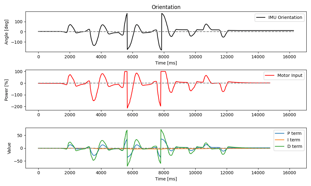
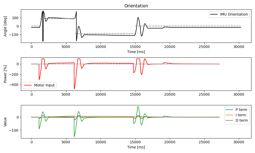
In Lab 6, I used IMU yaw measurements to implement a PID controller that points the car toward a particular heading and maintains that orientation.
Prelab
Much of my preparation for this lab was already in place from Lab 5 last week, where I had split up my code by the car's major components and written commands that control those systems via flags. I had also built several tools to help debug my position PID controller via Bluetooth, which I continued to use for orientation control for this lab.
At the end of Lab 5, I briefly noted an observation I had made about incorrect float encoding in the EString class.
I discovered [...] several odd rounding problems in the
EStringclass. I have not yet had time to investigate this further, but I suspect there may be something wrong with how floats are encoded into BLE messages.
For this lab, I decided to get to the bottom of these problems. It turns out that the version of EString.h we were provided at the beginning of the semester had two significant bugs in how it handled floats and doubles:
- Loss of negative signs for values between 0 and -1. This was found and posted to Ed Discussion (access restricted) by a classmate of mine.
- Dropping of zeros in the tenths and hundredths places. This was the problem I had observed last week.
The first problem caused values like -0.25 to appear as 0.25 when sent over BLE. The second turned very small values like 0.005 into 0.5 when the "leading" zeros of the decimal part of the float were truncated.
I devised a fix for the second problem, incorporated a fix for the first as suggested by my classmate, and posted an updated EString.h to Ed Discussion (access restricted) for others to use. The relevant changes, shown below, apply to the float and double signatures of append().
void append(float value) {
    int integer_part = (int)(value);
    int decimal_part = 1000 * abs(value - integer_part); //10^3 for 3 decimal places

    // Account for negative values
    if (value < 0) {
        strcat(char_array, "-");
    }

    // Write absolute integer value
    append(abs(integer_part));
    strcat(char_array, ".");

    // Account for leading zeros
    if (decimal_part < 100) {
        append(0);
    }
    if (decimal_part < 10) {
        append(0);
    }

    // Write decimal value
    append(decimal_part);
}
With this resolved, I was ready to move on to orientation control.
Tasks
Task 1: Orientation Input
Much like last week, I decided to use all three terms of a PID controller to implement robust and highly responsive orientation control. The mathematical form for this is the same as for position control, so that
except that the error
To measure orientation, specifically about the
The drift that I can observe in the gyroscope's readings are technically called bias. I'm not completely sure of all the factors that go into it, but bias is essentially an ever-so-slight imbalance in the gyro that yields a steady, erroneous rotational velocity that, when integrated over time, appears as a wandering orientation to the Artemis. Combined with a PID controller, this bias causes the car to slowly chase the erroneous reading at all times.
Because the bias seemed fairly constant when I tested it in Lab 2, one approach to mitigate drifting orientation could be to collect readings for a period of time, determine the bias velocity, and subtract this from future measurements while running PID control. I wasn't satisfied with this, though, because the approximation involved would still become worse over long run times.
Some digging into the IMU's datasheet and SparkFun's ICM 20948 Arduino library on GitHub revealed that the bias itself can actually be adjusted with registers. I considered this for a bit but decided to delve further. The datasheet kept mentioning a digital motion processor (DMP) which is included on the IMU board. One note stood out to me:
The DMP enables ultra-low power run-time and background calibration of the accelerometer, gyroscope, and compass, maintaining optimal performance of the sensor data for both physical and virtual sensors.
The emphasis here is mine. I immediately realized that the DMP unit on the IMU was exactly what I needed to avoid gyroscope drift, yet this feature is disabled by default. Pulling up the Arduino example sketch, Examples > ICM 20948 > Arduino > Example6_DMP_Quat9_Orientation, I inspected the necessary steps to enable the DMP and read orientation data in quaternion form. The sketch also pointed me to a quaternion visualization tool by ZaneL on GitHub. I had to make some updates to the tool to get it working with the latest version of Node.js, but was then able to generate a fun visual of the car's orientation.
After playing with the visualization for a while, I learned that the DMP exhibits a bit of drift at first, but then seems to correct for this as it sensor fuses the gyroscope with the accelerometer and compass/magnetometer. After a minute or two, the orientation readings are extremely steady, nothing at all like the wandering mess I saw in Lab 2. Thrilled with this result, I incorporated the DMP initialization routine into the setup() function on my Artemis.
// In setup():
bool success = true;

success &= (IMU.initializeDMP() == ICM_20948_Stat_Ok);

// Enable the DMP orientation sensor and set to 2000 dps
success &= (IMU.enableDMPSensor(INV_ICM20948_SENSOR_GAME_ROTATION_VECTOR) == ICM_20948_Stat_Ok);

// Configure DMP to output data at maximum ORD
success &= (IMU.setDMPODRrate(DMP_ODR_Reg_Quat6, 0) == ICM_20948_Stat_Ok);

// Enable the FIFO
success &= (IMU.enableFIFO() == ICM_20948_Stat_Ok);

// Enable the DMP
success &= (IMU.enableDMP() == ICM_20948_Stat_Ok);

// Reset DMP
success &= (IMU.resetDMP() == ICM_20948_Stat_Ok);

// Reset FIFO
success &= (IMU.resetFIFO() == ICM_20948_Stat_Ok);
Setting the DMP mode to INV_ICM20948_SENSOR_GAME_ROTATION_VECTOR sets the IMU polling rate to 1.1 kHz and the maximum rotational velocity for the gyroscope to 2000 degrees per second (dps). This should be more than enough for PID control of the sort of maneuvers my car is likely to ever perform.
I could now take orientation measurements from the DMP as quaternions and convert these to an Euler angle for rotation about the record_dmp_data() function.
float yaw_gy = 0;

double qw;
double qx;
double qy;
double qz;
double siny;
double cosy;

void record_dmp_data() {
    icm_20948_DMP_data_t dmp;
    IMU.readDMPdataFromFIFO(&dmp);

    // Check if the IMU has data
    if ((IMU.status != ICM_20948_Stat_Ok) && (IMU.status != ICM_20948_Stat_FIFOMoreDataAvail)) return;

    // Check for Quat6 orientation data
    if ((dmp.header & DMP_header_bitmap_Quat6) <= 0) return;

    // Scale to +/- 1
    qx = ((double) dmp.Quat6.Data.Q1) / 1073741824.0; // Convert to double. Divide by 2^30
    qy = ((double) dmp.Quat6.Data.Q2) / 1073741824.0; // Convert to double. Divide by 2^30
    qz = ((double) dmp.Quat6.Data.Q3) / 1073741824.0; // Convert to double. Divide by 2^30

    // Start converting quaternion to Euler angles
    qw = sqrt(1.0 - min(((qx * qx) + (qy * qy) + (qz * qz)), 1.0));

    // Yaw (z-axis rotation)
    siny = 2.0 * (qw * qz + qx * qy);
    cosy = 1.0 - 2.0 * (qy * qy + qz * qz);
    yaw_gy = (float)(atan2(siny, cosy) * 180.0 / PI);
}
An added benefit of this quaternion approach is that the resulting yaw value incorporates slight misalignments in the other axes. This is great because I have no way to confirm whether my IMU is attached perfectly level to the car with respect to the ground.
Task 2: PID Terms
With the orientation measurements well sorted, I implemented the PID controller. This was mostly the same as Lab 5, except that I used readings for yaw instead of distance while adding a pid_ori_control() function.
float pid_angle_data[DATA_SIZE] = {0};

// Set by BLE command
float Sc_ori = 0.1;
float Kp_ori = 0.01;
float Ki_ori = 0;
float Kd_ori = 0;

int pid_ori_target = 0;
int pid_ori_recip = 0;

void pid_ori_control() {
    last_pid_time = current_pid_time;
    current_pid_time = micros() / 1.e6; // secs
    pid_dt = current_pid_time - last_pid_time;

    last_error = current_error;
    current_error = yaw_gy - pid_ori_target;

    // Set target reciprocal at 180 degrees offset
    pid_ori_recip = pid_ori_target - (pid_ori_target < 0 ? -1 : 1) * 180;

    if (abs(current_error) > 180.0) {
        // Prevent sudden jumps in angle when crossing the +/- 180 boundary
        current_error += (pid_ori_recip - yaw_gy) / abs(pid_ori_recip - yaw_gy) * 360.0;
    }

    P_term = Kp_ori * current_error;

    error_integral = error_integral + current_error * pid_dt;
    I_term = Ki_ori * error_integral;

    D_term = Kd_ori * (current_error - last_error) / pid_dt;

    last_filtered_D_term = filtered_D_term;
    filtered_D_term = D_LPF_ALPHA * D_term + (1-D_LPF_ALPHA) * last_filtered_D_term;

    speed = Sc_ori * (P_term + I_term + filtered_D_term);

    if (flag_record_pid) {
        pid_time_data[pid_data_i] = current_pid_time;
        pid_angle_data[pid_data_i] = yaw_gy;
        pid_p_data[pid_data_i] = P_term;
        pid_i_data[pid_data_i] = I_term;
        pid_d_data[pid_data_i] = D_term;
        pid_df_data[pid_data_i] = filtered_D_term;

        pid_data_i++;

        if (pid_data_i >= DATA_SIZE) {
            flag_record_tof = false;
            flag_record_pid = false;
        }
    }

    if (!flag_enable_motors) return;

    if (abs(speed) < ORIENT_THRESHOLD) {
        stopMotors();
        return;
    }

    // Invert speeds for differential steering
    driveMotors(speed, -speed);
}
For the D (derivative) term, it would normally be inefficient to take the derivative of a yaw value integrated over time from the gyroscope's angular velocity data. But because the DMP provides me with discrete angle readings, I do indeed have to take the derivatives of these.
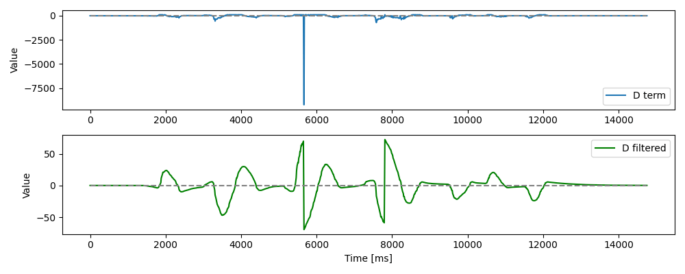
As with the position controller in Lab 5, I found it absolutely necessary to add a heavy low-pass filter (LPF) for the derivative term to avoid sending outlandish values to the motor controllers. The plot below shows the effect.

When I considered derivative kick in Lab 5, I concluded that my significant LPF was enough to dampen any such behavior. This time, I added kick protection to test it directly. To do this, I changed the PID controller to find the D term from the derivative of the yaw reading rather than the error.
 D_term = Kd_ori * (current_error - last_error) / pid_dt;
!D_term = Kd_ori * (yaw_gy - last_yaw_gy) / pid_dt;
This way, changing the setpoint on the fly wouldn't send a large spike through to the motor controllers. However, in practice, I found exactly what I had predicted last week to be true: the LPF cuts down on the spikes so dramatically, that the kick protection does very little to change the behavior of the car.
Task 3: Implementation
After many experiments and adjustments, my tuned position PID controller now has the following gains:
Kpof 0.4Kiof 0.08Kdof 0.6
Disturbing the car from its resting setpoint causes it to snap back fairly quickly. I used a wooden table for the demos in this lab because after I taped my car's wheels to help it overcome friction for turning, my flooring turned out to be a bit too slippery, so I needed a slightly rougher surface. There is still some overshoot due to slip, however.

As in Lab 5, I kept the implementation for this lab strictly flag-based. That way, I can selectively enable various components and systems on my car, and update PID gains and such, all on the fly. A particularly useful consequence of this is that I can update the orientation setpoint while the PID controller is running. The video below shows targets of 0, 90, and -90 degrees from the initial state.

While the combination of position and orientation control were not expected in this lab, I did start to think a out how this might work in the future. The car would need to be driving, say, forward with an orientation setpoint of 0 degrees. That alone should yield a straight trajectory. Then, a new orientation setpoint would be sent over BLE and the PID controller would respond to this by adjusting the speed of each motor relative to the active forward input.
Depending on the amount of change in the setpoint, the speed adjustment for simultaneous position and orientation control may be small, resulting in a curved path, or large, resulting in a considerable turn followed by a straight path in a new direction. Either way, the PID controller needs to make relative adjustments, unlike these last two labs where the adjustments were absolute and not a function of previous inputs.
Optional 5000-Level: Wind-Up Protection
Just like in Lab 5, I implemented integrator wind-up protection by limiting the error integration to a maximum of 300% speed. This protection was active for all the demos above.
#define INTEGRAL_THRESHOLD 300

void pid_ori_control() {
    ...

    // Constrained integral of error
    error_integral = constrain(
        error_integral + current_error * pid_dt,
        -INTEGRAL_THRESHOLD, INTEGRAL_THRESHOLD
    );

    ...
}
Without this protection, the car would spin wildly out of control as small errors grow into oblivion. What little I saw of this consequence in my testing makes me uncomfortable forcing the behavior for the sake of a demo, so let's just agree that wind-up protection is a good idea.
An alternative method for dealing with wind-up might be to integrate error over only a finite window of recent time, as opposed to all time as I do currently. This would require a more complex data storage solution, however, which would take more memory and slow down the PID controller.
Conclusion
This lab, although quite similar in structure to the last one, gave me an opportunity to get much better acquainted with the IMU and its capabilities. If not for my frustration over the gyroscope drift earlier in the semester, I likely would not have figured out how to use the DMP and significantly improved my car's sense of orientation at this point in the project.
Similarly, had I not been annoyed at the odd float encoding issues I saw when sending data over BLE last week, I would not have found the bugs in EString, the fixes to which I can only hope will benefit my classmates and future students in the course.