In Lab 5, I used ToF distance measurements to implement a PID controller that drives the car toward a wall and stops just short of crashing into it.
Prelab
I wanted to challenge myself a bit with this lab and decided to strive for full PID control of the car's position. To pull this off, I knew I would eventually be tuning three different gains,
First, I separated the code for each major system and component into respective C++ header files.
ble.hpp: handles BLE connections and commandsimu.hpp: processes IMU data and performs calculationstof.hpp: manages sensor juggling and processes ToF datamotors.hpp: controls motors by translating speeds to PWMcmd_types.h: holds theCommandTypesenumflags.h: defines various boolean flags that control systemsutil.hpp: declares generic helper functions
This left only the standard Arduino setup() and loop() in my core artemis.ino file. I did all this because I got tired of scrolling through a long wall of code to make changes. Normally, I would go one step further and move things into classes, but that's not so great for performance on microcontrollers. So no classes this time, but splitting things up for my sanity and letting the compiler stitch them back together is a good step forward.
Next, with a better structure in hand, I added several new commands to ble.hpp that control various aspects of the PID-related logic.
SET_PID_POS_GAINS: takes four floats—a speed factorSc, and the positional PID gainsKp,Ki, andKdENABLE_MOTORS: allow writing PWM values to the motorsDISABLE_MOTORS: block motor PWM valuesSTART_TOF_RANGING: turn on the ranging function of the ToF sensorsSTOP_TOF_RANGING: turn off ToF rangingSTART_PID_POS_CONTROL: perform PID position control for a brief timeSTOP_PID_POS_CONTROL: end PID control and stop the motors if runningSTART_PID_POS_WITH_DATA: perform PID control while saving all valuesSTOP_PID_POS_WITH_DATA: end PID controlSEND_PID_DATA: send recorded PID values over BLE
Most of these commands simply flip boolean flags defined in flags.h, which are then used by various functions to conditionally perform actions. For example, START_PID_POS_WITH_DATA looks like this:
// In handle_command():
case START_PID_POS_WITH_DATA: {
    // Only continue if not already active
    if (flag_pid_pos && flag_record_tof) return;

    // Remove all previously stored data
    clear_tof_data();
    clear_pid_data();

    // Get target distance from BLE command
    success = robot_cmd.get_next_value(pid_pos_target);
    if (!success) return;

    // Set flags
    flag_record_tof = true;
    flag_record_pid = true;
    flag_pid_pos = true;

    break;
}
Once the PID maneuver is complete, I can stop everything again with STOP_PID_POS_WITH_DATA:
// In handle_command():
case STOP_PID_POS_WITH_DATA: {
    // Only continue if still active
    if (!flag_pid_pos && !flag_record_tof) return;

    // Reset flags and values
    flag_record_tof = false;
    flag_record_pid = false;
    flag_pid_pos = false;
    pid_pos_target = 0;
    pid_pos_start_time = 0;

    // Stop motors if still running
    stopMotors();

    break;
}
I can then send the recorded data using SEND_PID_DATA.
// In handle_command():
case SEND_PID_DATA: {
    uint16_t i;

    for (i = 0; i < DATA_SIZE; i++) {
        if (tof_time_data[i] < 0.1) break;

        tx_estring.clear();
        tx_estring.append("To:");
        tx_estring.append(tof_time_data[i] * 1000.);
        tx_estring.append(",Do:");
        tx_estring.append(tof_data[i]);
        tx_estring.append(",Ti:");

        // PID data here

        tx_characteristic.writeValue(tx_estring.c_str());
    }

    break;
}
On the Python side, the new commands allow a workflow as follows.
# Connect to the Artemis over Bluetooth
nano = Artemis()
nano.start()

# Send the PID gains over BLE
nano.command(CMD.SET_PID_POS_GAINS, f'{Sc}|{Kp}|{Ki}|{Kd}')

# Start ToF ranging
nano.command(CMD.START_TOF_RANGING)

# Enable the motors
nano.command(CMD.ENABLE_MOTORS)

# Start PID control, then wait for the car to maneuver
nano.command(CMD.START_PID_POS_WITH_DATA, '200') # target in mm

# Stop PID control
nano.command(CMD.STOP_PID_POS_WITH_DATA)

# Send PID data back to Python
nano.command(CMD.SEND_PID_DATA)
nano.collect()

# Process data in nano.data...
Should the BLE connection fail during a PID test, I have a failsafe mechanism that disables the motors and sensors immediately after the control loop.
// In loop():
// While BLE is connected
while (central.connected()) {
    ...
}

// Stop everything when BLE disconnects
flag_record_imu = false;
flag_record_tof = false;
flag_pid_pos = false;
stopMotors();
TOF1.stopRanging();
TOF2.stopRanging();
Tasks
Task 1: Frequency
The ToF sampling frequency is dependent on the timing budget. Because the goal here is to make a fast PID controller that can stop the car from running into walls, I opted for a 20 ms timing budget, which is the fastest supported by our ToF sensors in long mode and yields a frequency of 50 Hz. To confirm this in practice, I printed times to the serial monitor as fast as possible while conditionally reading ToF data, similar to Lab 3.
while (central.connected()) {
    // Read ToF data when either flag is set
    if (flag_tof_ranging || flag_record_tof) {
        if (TOF1.checkForDataReady()) {
            record_tof_data(TOF1);

            // Print times during ToF readings
            Serial.print('ToF:');
            Serial.println(micros());
        }

        if (TOF2.checkForDataReady()) {
            record_tof_data(TOF2);
        }
    }
}
After a few seconds of this, the serial monitor showed an approximate interval of 21.7 ms between ToF readings, corresponding to a frequency of 46 Hz. That's just shy of the expected rate, and would likely be too slow for a PID controller.
Since the ToF sensors' short mode only supports distances up to roughly 1.3 m, I decided to switch to long mode, which supports up to 4 m. Together with a 20 ms timing budget, I knew the ToF sensors wouldn't be super accurate in this configuration, but they would be faster and reach pretty far.
Task 2: PI Position Control
A PID controller is a combination of proportional, integral, and derivative control terms to form the motor input function
where
A P controller is a good start but will often experience considerable steady state error. A PI controller attempts to fix this by pushing the motors more and more until the error is eliminated. A PID controller improves upon the situation even further by damping the motor input in response to rapid changes in sensor readings, such as when the car gets close to the wall. Generally, a PID controller is a classic mechanism and worth exploring.
I started building the PID controller by focusing on the P (proportional) term. For Lab 4, I had already written a function, driveMotors(), that takes motor speeds in percentages (between 0 and 100) and translates them to PWM values. While implementing the proportional controller, I therefore chose values of
To implement proportional control, I added a pid.hpp C++ header and a pid_pos_control() function.
float pid_time_data[DATA_SIZE] = {0};
float pid_distance_data[DATA_SIZE] = {0};
float pid_p_data[DATA_SIZE] = {0};

uint16_t pid_data_i = 0;

// Set by BLE command
float Sc_pos = 0;
float Kp_pos = 0;
int pid_pos_target = 0;

float current_pid_time = 0;
float current_error = 0;
float P_term = 0;
float speed = 0;

void pid_pos_control() {
    // Update current time
    current_pid_time = micros() / 1.e6; // secs

    // Determine error from most recent position and set point
    current_error = current_tof_reading - pid_pos_target;

    // Calculate P term
    P_term = Kp_pos * current_error;

    speed = Sc_pos * P_term;

    if (flag_record_pid) {
        pid_time_data[pid_data_i] = current_pid_time;
        pid_distance_data[pid_data_i] = current_tof_reading;
        pid_p_data[pid_data_i] = P_term;

        pid_data_i++;

        // Out of memory
        if (pid_data_i >= DATA_SIZE) {
            flag_record_tof = false;
            flag_record_pid = false;
        }
    }

    if (!flag_enable_motors) return;

    // Only drive motors if the speed meets the minimum threshold
    if (abs(speed) < MOTOR_THRESHOLD) {
        stopMotors();
        return;
    }

    driveMotors(speed);
}
I then called the PID function in the BLE control loop.
while (central.connected()) {
    // Read ToF data
    ...

    // Perform PID
    if (flag_tof_ranging && flag_pid_pos) {
        pid_pos_control();
    }
}
Setting the speed scale Sc to 0.5 for half speed and the proportional gain Kp to 0.05 as planned, I tested the P controller for a set point of 300 mm.
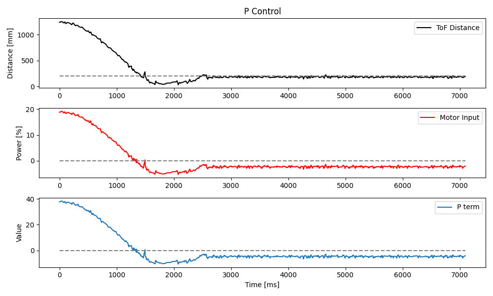
To add the I (integral) term, I kept track of the previous PID loop time to calculate dt and use it to sum error over all time.
float pid_i_data[DATA_SIZE] = {0};

// Set by BLE command
float Ki_pos = 0;

float pid_dt = 0;
float last_pid_time = 0;
float current_pid_time = 0;
float error_integral = 0;
float I_term = 0;

void pid_pos_control() {
    ...

    // Calculate dt
    pid_dt = current_pid_time - last_pid_time;
    last_pid_time = current_pid_time;

    ...

    // Integrate error
    error_integral = error_integral + current_error * pid_dt;

    I_term = Ki_pos * error_integral;

    speed = Sc_pos * (P_term + I_term);

    if (flag_record_pid) {
        ...
        pid_i_data[pid_data_i] = I_term;
        ...
    }

    ...
}
After playing around with the integral gain Ki, I settled on 0.007 and tested the new PI controller at the same set point of 300 mm.
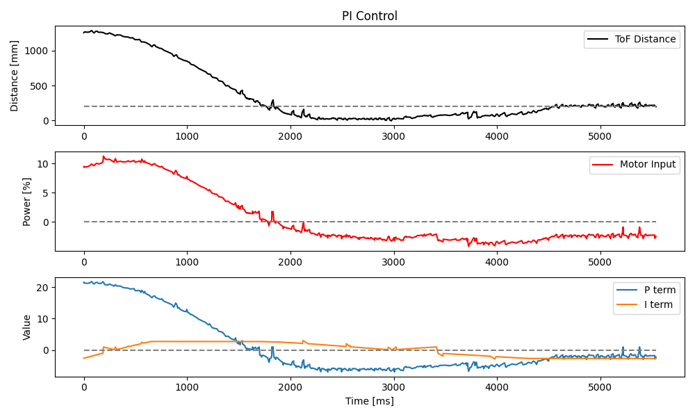
Task 3: PID Loop Rate
Before continuing on to the D (derivative) term, I needed to know how fast the PID controller runs when decoupled from the ToF sensors. To that end, I had the BLE control loop print times to the serial monitor as fast as possible.
while (central.connected()) {
    // Read ToF data
    ...

    // Perform PID
    if (flag_tof_ranging && flag_pid_pos) {
        // Print times as fast as PID will run
        Serial.print('PID:');
        Serial.println(micros());

        pid_pos_control();
    }
}
From this, I found that the PID control loop interval was 3.57 ms, which is a frequency of about 280 Hz, six times faster than the rate of ToF readings. Smooth derivative control would therefore require extrapolation to bridge the gaps in distance measurements.
Task 4: Distance Extrapolation
To extrapolate distance, I first added global variables to store the last two ToF measurements. From these, I could then calculate the slope between them, then multiply that by the time elapsed since the most recent measurement.
uint16_t current_tof_reading = 0;
uint16_t last_tof_reading = 0;
float current_tof_time = 0;
float last_tof_time = 0;
float tof_slope = 0;

float tof_dt = 0;
float tof_distance = 0;

void record_tof_data(SFEVL53L1X &TOF) {
    last_tof_reading = tof_reading;
    last_tof_time = tof_time;

    tof_reading = TOF.getDistance();
    tof_time = micros() / 1.e6; // secs

    tof_slope = (tof_reading - last_tof_reading) / (tof_time - last_tof_time);

    ...
}

void pid_pos_control() {
    ...

    // Calculate dt for ToF sensor readings
    tof_dt = current_pid_time - current_tof_time; // secs
    tof_distance = tof_slope * tof_dt + current_tof_reading;

    // Find error from extrapolated distance
    current_error = tof_distance - pid_pos_target;

    ...
}
The effect of the extrapolation is a relative smoothing out of the rather step-like data generated by intermittent ToF readings. I say relative because the extrapolation gets its "prediction" wrong any time there are sudden changes in direction of the data, thereby causing little spikes.
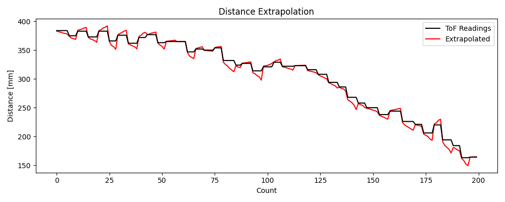
Task 5: PID Control
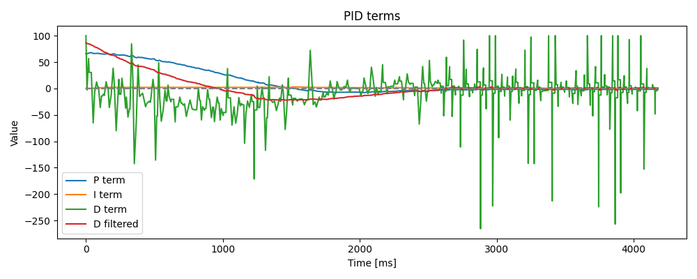
With distance extrapolation in place, I modified pid_pos_control() to add the derivative term to the PID controller by finding the change in error since the last step and dividing by dt. I then also added a strong low-pass filter (LPF) because the ToF data is quite noisy in long mode and the resulting derivative is highly reactive, amplifying the spiky behavior seen in the extrapolation. The LPF helps to calm the derivative control down to more reasonable values.
#define D_LPF_ALPHA 0.015

float pid_d_data[DATA_SIZE] = {0};
float pid_df_data[DATA_SIZE] = {0};

// Set by BLE command
float Kd_pos = 0;

float last_error = 0;
float D_term = 0;
float filtered_D_term = 0;
float last_filtered_D_term = 0;

void pid_pos_control() {
    ...

    // Differentiate error
    D_term = Kd_pos * (current_error - last_error) / pid_dt;
    last_error = current_error;

    filtered_D_term = D_LPF_ALPHA * D_term + (1-D_LPF_ALPHA) * last_filtered_D_term;
    last_filtered_D_term = filtered_D_term;

    speed = Sc_pos * (P_term + I_term + filtered_D_term);

    if (flag_record_pid) {
        ...
        pid_distance_data[pid_data_i] = tof_distance;
        pid_d_data[pid_data_i] = D_term;
        pid_df_data[pid_data_i] = filtered_D_term;
        ...
    }
}
After some tuning, I chose a Kd of 0.02 and tested the finished PID controller at 50% speed for the same set point of 300 mm.
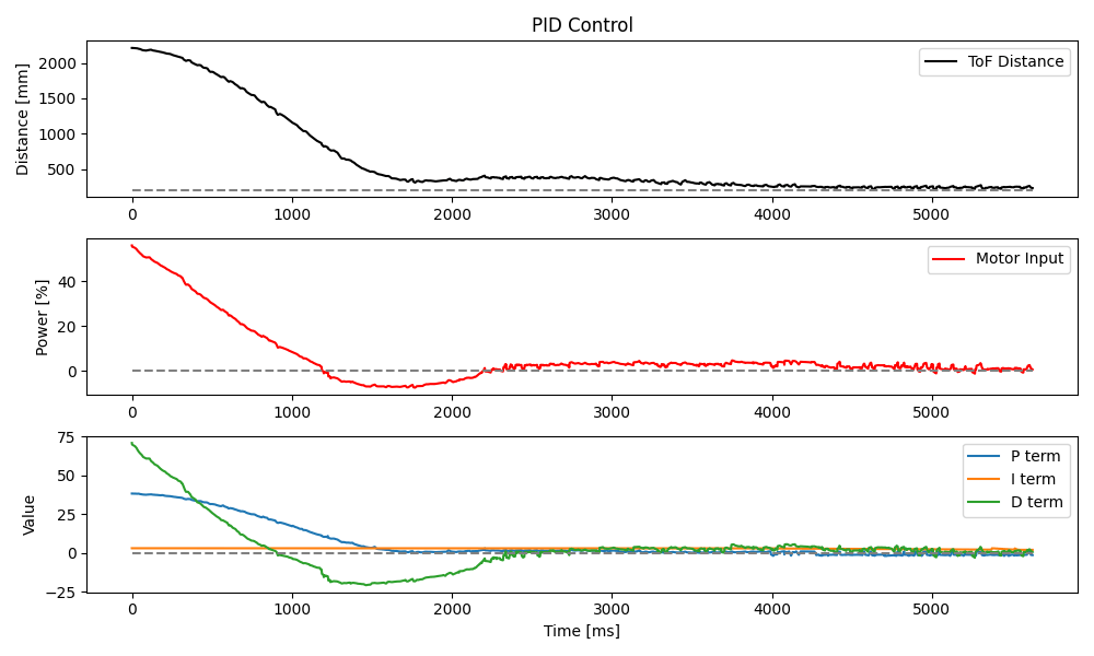
I then bumped the speed up to 80% and ran the test again.
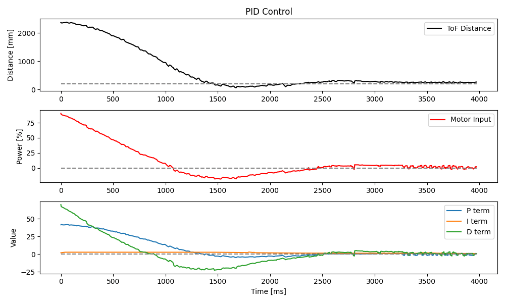
Lastly, I set the speed to 100% for a full steam attempt.
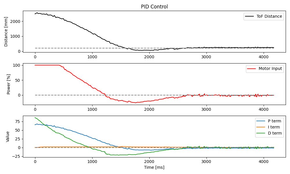
As I ramped up the speed of the car, I noticed that traction between the wheels and my hardwood floor became an issue when the car tried to stop or reverse directions near the set point. The result was something of a tilt motion for which the car did not have a correction mechanism. Orientation control will hopefully account for this in the future, but I also note that doing this sort of experimentation on carpet may be better.
From these tests, I decided that derivative kick wasn't really an issue. Though kick is worth considering, the effects of the LPF were already so significant that there was little point in pursuing a treatment for kick on top of it. The plot below shows the LPF in action. Note the green and red curves.
Along similar lines, I let the motors coast when the input
Task 6: Speed
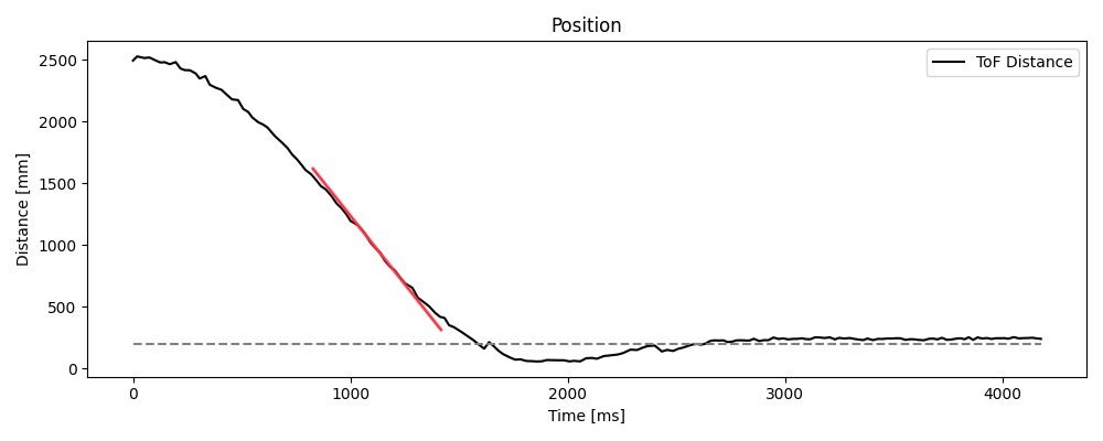
At full speed, my car is able to close a 2.5 m distance to the wall in 1.5 seconds. The maximum speed during this maneuver is roughly 2 m/s, found from the highest rate of change of the car's position over its runtime. The speed is shown as a slope on the position plot below.
Optional 5000-Level: Wind-Up Protection
While tuning the integral term of the PID controller, I quickly noticed that integrator wind-up would be a problem. The plot below shows an example of how the integral term can vastly outscale the proportional term.
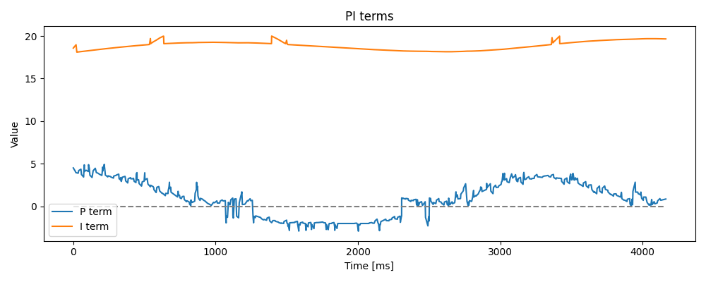
This happens because errors are summed over time, and can self-perpetuate a larger and larger running integration, quickly ballooning to unreasonable values. Once the error integration has built up, it takes equally large values of the opposite sign to reduce the sum again.
To prevent this kind of wind-up, I added a constraint onto the error integration so it cannot exceed 300% speed in either direction.
#define INTEGRAL_THRESHOLD 300

void pid_pos_control() {
    ...

    // Constrained integral of error
    error_integral = constrain(
        error_integral + current_error * pid_dt,
        -INTEGRAL_THRESHOLD, INTEGRAL_THRESHOLD
    );

    ...
}
With the wind-up heavily constrained, the integral term contributes only a little to the overall PID output, as can be seen in the earlier 100% speed PID test, shown again here.

This is preferable to letting the controller spiral out of control and send the car flying across the room at the slightest touch of error.
Conclusion
This lab made me appreciate PID controllers more. I have studied them in past courses, but building one from scratch and then tuning it for a real-world target scenario was educational. This process did not come without issues, however.
For one thing, I discovered that my approach to storing time data as microseconds, then dividing those values by 1e6 upon sending them over Bluetooth causes several odd rounding problems in the EString class. I have not yet had time to investigate this further, but I suspect there may be something wrong with how floats are encoded into BLE messages.
Another issue I faced is that I had trouble extrapolating the distance values at first because I wasn't clearing the ToF ranging interrupts between readings. I had seen elsewhere that starting and stopping the ranging with every measurement wasn't completely necessary, but apparently it does have some odd side effects. In my case, the ToF sensors would repeat readings several times when the interrupt wasn't cleared. So when I tried to calculate slopes between recent values, I kept getting zeros.
It'll be interesting to add orientation soon. I can tell the car needs it. The motors, gearboxes, and even the wheels are all too inconsistent to maintain a true course for very long.