In Lab 4, I added two dual motor drivers to the Artemis, replaced the factory circuitry in the RC car with my own, and tested and tuned the car's motors.
Prelab
Before the lab, I planned out the connections between the Artemis, the car's motors and two Pololu dual motor drivers, and our 3.7 V batteries. In Lab 3, I had soldered one of the ToF XSHUT connections to pin 2 on the Artemis, so I decided to consolidate the new motor driver connections on the same side of the Artemis board by using pins 0, 1, 3, and 4, all of which support PWM.
While connecting the in and output pins of the motor drivers, I settled on using short, twisted pairs of wires to avoid interference. I also refrained from placing I2C cables near motor power or control wires for the same reason. I then placed the IMU and ToF sensors toward the outer edges of the car to maximize distance to the center-mounted motors and their magnets.
Whenever possible, I used stranded wire to make the connections less likely to fail from bending or twisting.
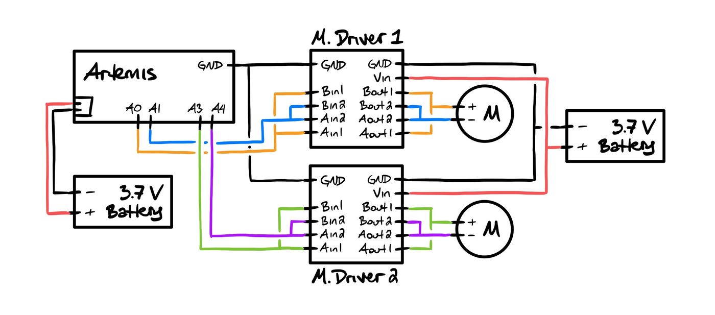
I had already prepared one 3.7 V battery in Lab 3, but I found it would be best to use more than a single battery to power the car. Spinning up the DC motors can cause surges in current draw that may disrupt the power supply to the Artemis and potentially trip its reset circuit. To avoid such transient effects, I dedicated a second 3.7 V battery to the motors, which also has the added bonus of increasing the car's overall battery life by doubling the capacity.
Tasks
Task 1: Disassembly
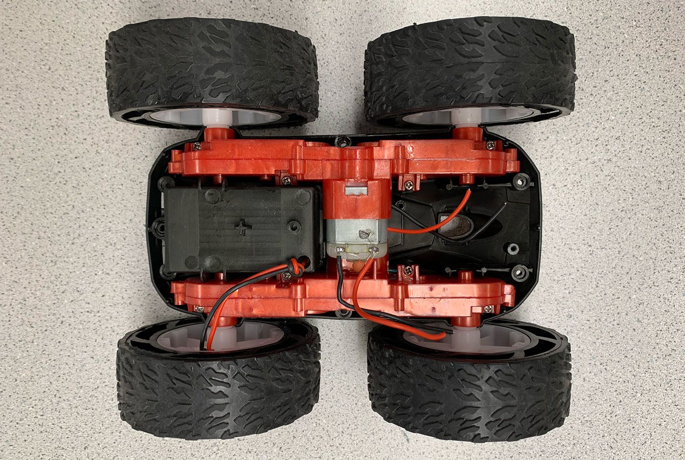
After taking the car apart and cutting out the factory PCB, I was left with a good deal of empty space for my own components.
Task 2: First Motor Driver
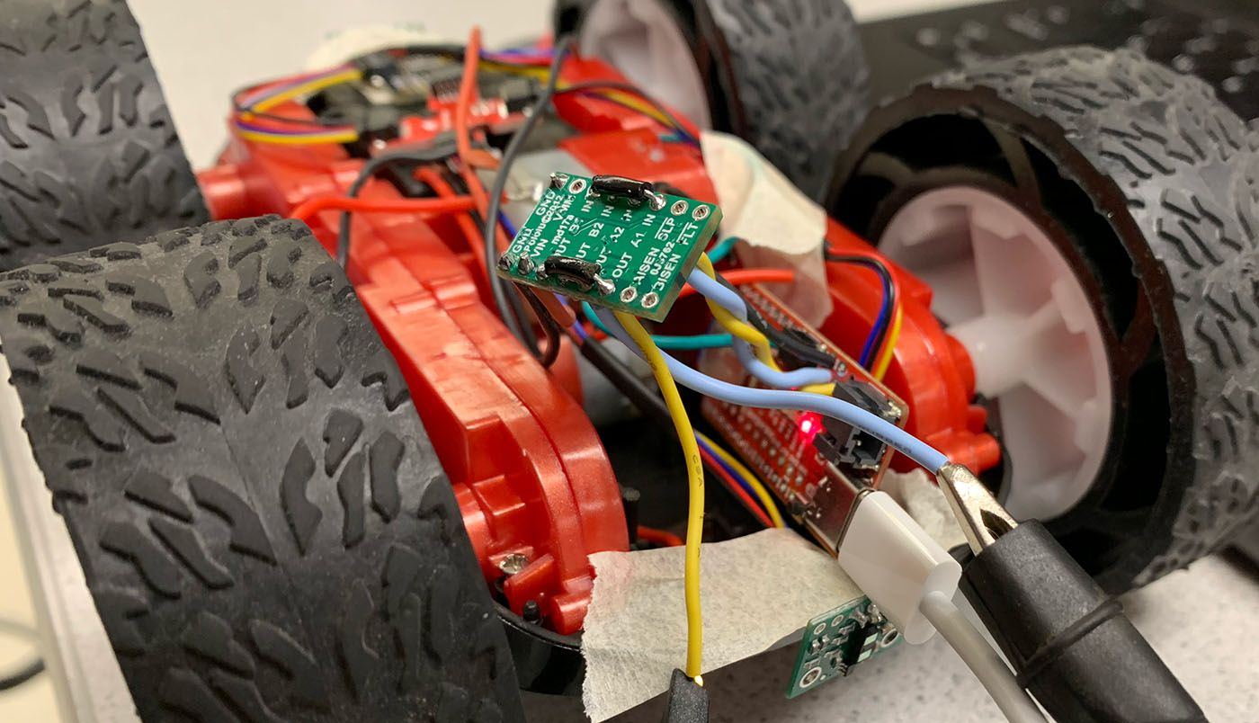
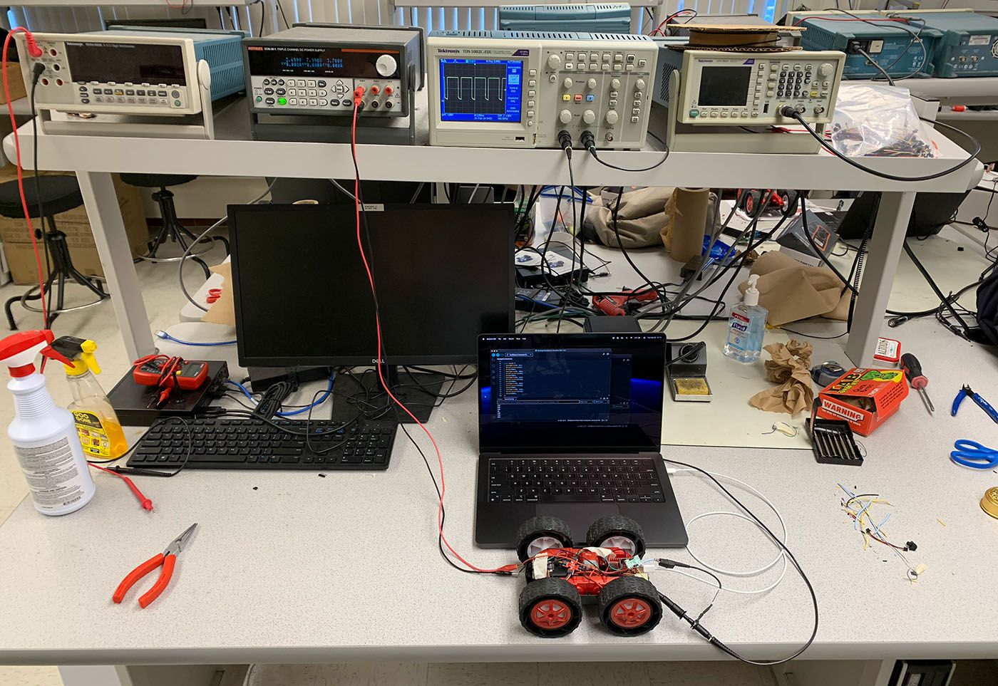
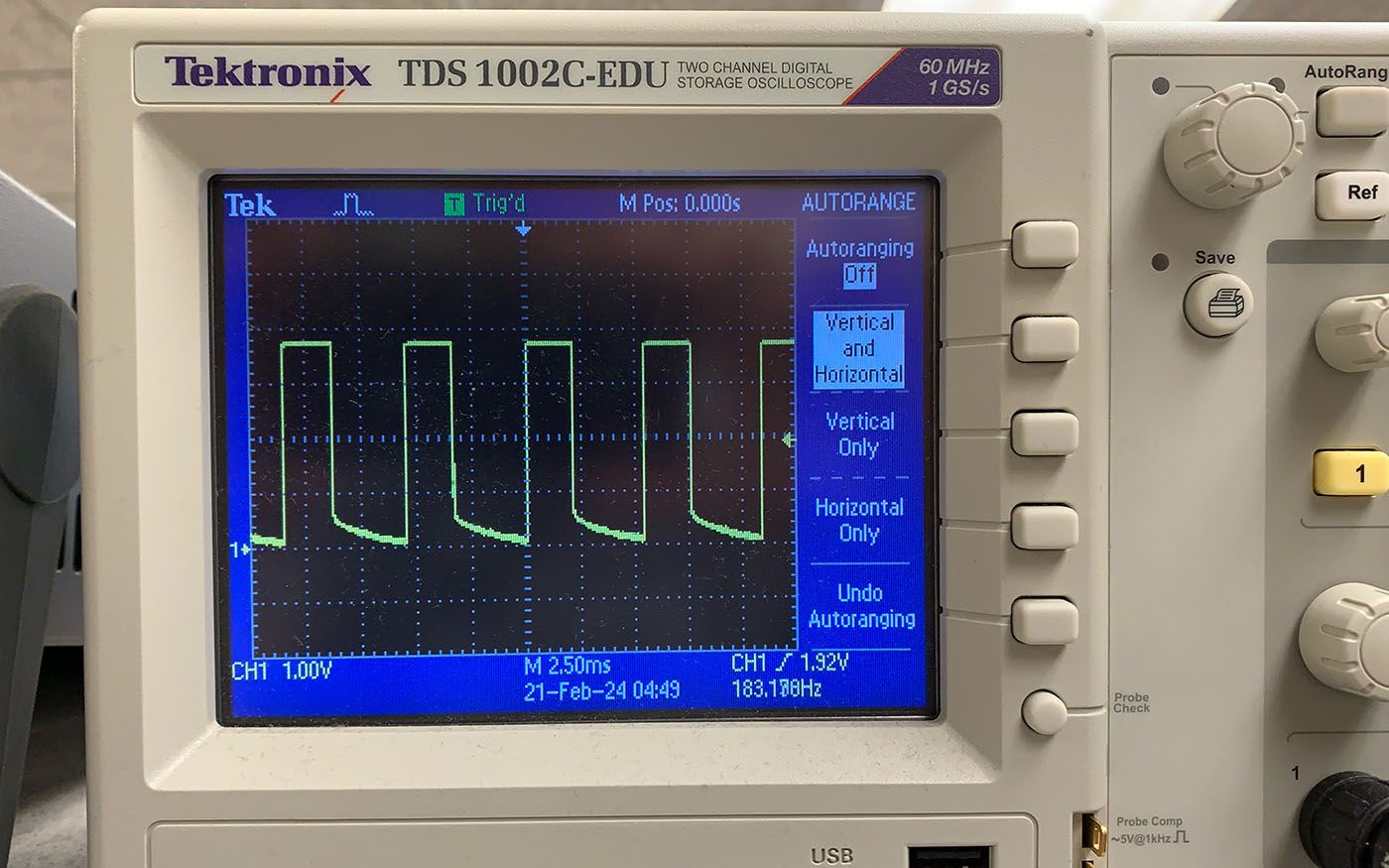
After soldering the necessary connections for the first of the two motor drivers, including inputs from pins 0 and 1 on the Artemis, I loosely placed all my components into the car's chassis. I then connected the output of the motor driver to an oscilloscope while powering Vin using an external power supply.
To mimic the battery that will eventually take the power supply's place, I set a constant output voltage of 3.7 V and a current of 1.5 A. Our batteries, which have capacities of 850 mAh and discharge ratings of 25C, actually support currents up to roughly 21 A. For testing, however, I felt that 1.5 A was sufficient.
Task 3: PWM
Using Arduino's analogWrite(), I tested the first motor driver's connections by cycling the Artemis through several PWM duty cycles while monitoring the motor-side output with the oscilloscope.
#define PWM_PIN 0

void setup() {
    pinMode(PWM_PIN, OUTPUT);
    analogWrite(PWM_PIN, 0);
}

void loop() {
    analogWrite(PWM_PIN, 50);
    delay(2000);

    analogWrite(PWM_PIN, 100);
    delay(2000);

    analogWrite(PWM_PIN, 150);
    delay(2000);

    analogWrite(PWM_PIN, 200);
    delay(2000);

    analogWrite(PWM_PIN, 250);
    delay(2000);
}
The video below shows the output cycling in action.
Task 4: Motors
Next, I soldered the first motor driver to one of the car's motors and used analogWrite() again to get the wheels on one side of the car to spin in both directions with a bit of delay in between.
#define MOTOR_A_FWD 0
#define MOTOR_A_BWD 1

void setup() {
    pinMode(MOTOR_A_FWD, OUTPUT);
    pinMode(MOTOR_A_BWD, OUTPUT);
}

void loop() {
    analogWrite(MOTOR_A_FWD, 255);
    delay(5000);

    analogWrite(MOTOR_A_FWD, 0);
    delay(1000);

    analogWrite(MOTOR_A_BWD, 255);
    delay(5000);

    analogWrite(MOTOR_A_BWD, 0);
    delay(1000);
}
Task 5: Battery Power
The car came with a battery connector wired through a hole in the car's battery compartment. Having cut the battery cable off at the factory PCB earlier, I could now solder the loose ends to the first motor driver.
In Lab 3, I had fitted a 3.7 V battery with a JST connector. I realized in this lab that such a permanent connection wasn't ideal. Instead, I took the JST connector back off and soldered it to one of the charging couplers that come with the 3.7 V batteries. I then plugged the resulting JST-to-coupler dongle into the Artemis, drilled a new hole into the battery compartment, and ran the dongle through it.
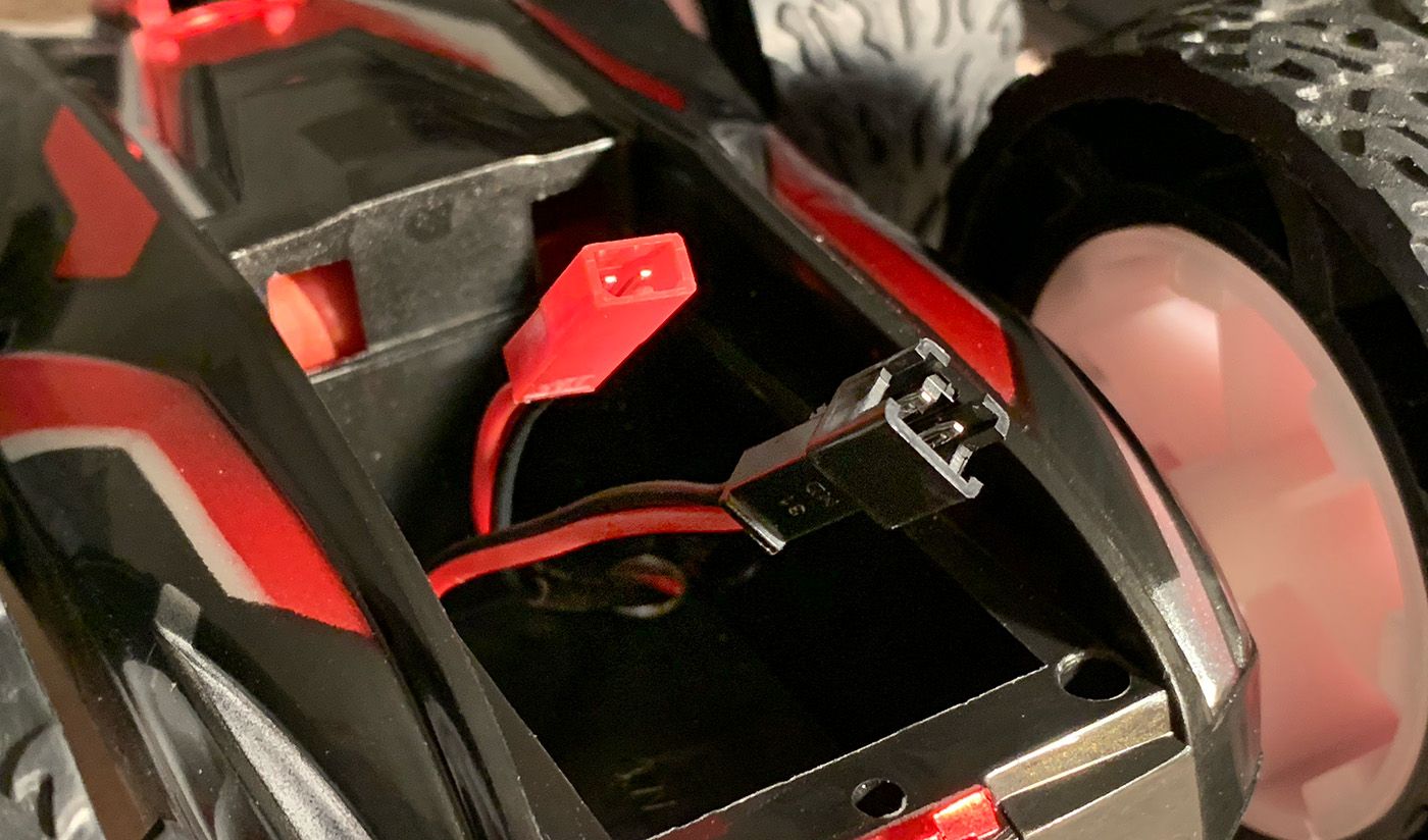
The result is a pair of battery connectors—one for the Artemis, one for the motors—that emanate from the battery compartment and allow quick swapping of batteries at any time. With this sorted, I can charge my batteries separately and directly, without having to connect the Artemis to my laptop.
Task 6: Another Driver
With one dual motor driver connected, working, and powered by battery, I soldered a second motor driver much the same way, this time to pins 3 and 4 on the Artemis. I then connected both drivers to the same battery cable and used analogWrite() to test both motors.
#define MOTOR_LEFT_FWD 0
#define MOTOR_LEFT_BWD 1
#define MOTOR_RIGHT_FWD 4
#define MOTOR_RIGHT_BWD 3

void setup() {
    pinMode(MOTOR_LEFT_FWD, OUTPUT);
    pinMode(MOTOR_LEFT_BWD, OUTPUT);
    pinMode(MOTOR_RIGHT_FWD, OUTPUT);
    pinMode(MOTOR_RIGHT_BWD, OUTPUT);
}

void loop() {
    analogWrite(MOTOR_LEFT_FWD, 100);
    analogWrite(MOTOR_RIGHT_FWD, 100);
    delay(5000);

    analogWrite(MOTOR_LEFT_FWD, 0);
    analogWrite(MOTOR_RIGHT_FWD, 0);
    delay(1000);

    analogWrite(MOTOR_LEFT_BWD, 100);
    analogWrite(MOTOR_RIGHT_BWD, 100);
    delay(5000);

    analogWrite(MOTOR_LEFT_BWD, 0);
    analogWrite(MOTOR_RIGHT_BWD, 0);
    delay(1000);
}
After precariously balancing the car on two cardboard boxes and then plugging in both batteries, I let the motors spin at low speed for a few seconds.
Task 7: Back Together Again
Before properly driving the car on the ground, I finalized the arrangement of all my components and secured them as much as I could in the chassis.
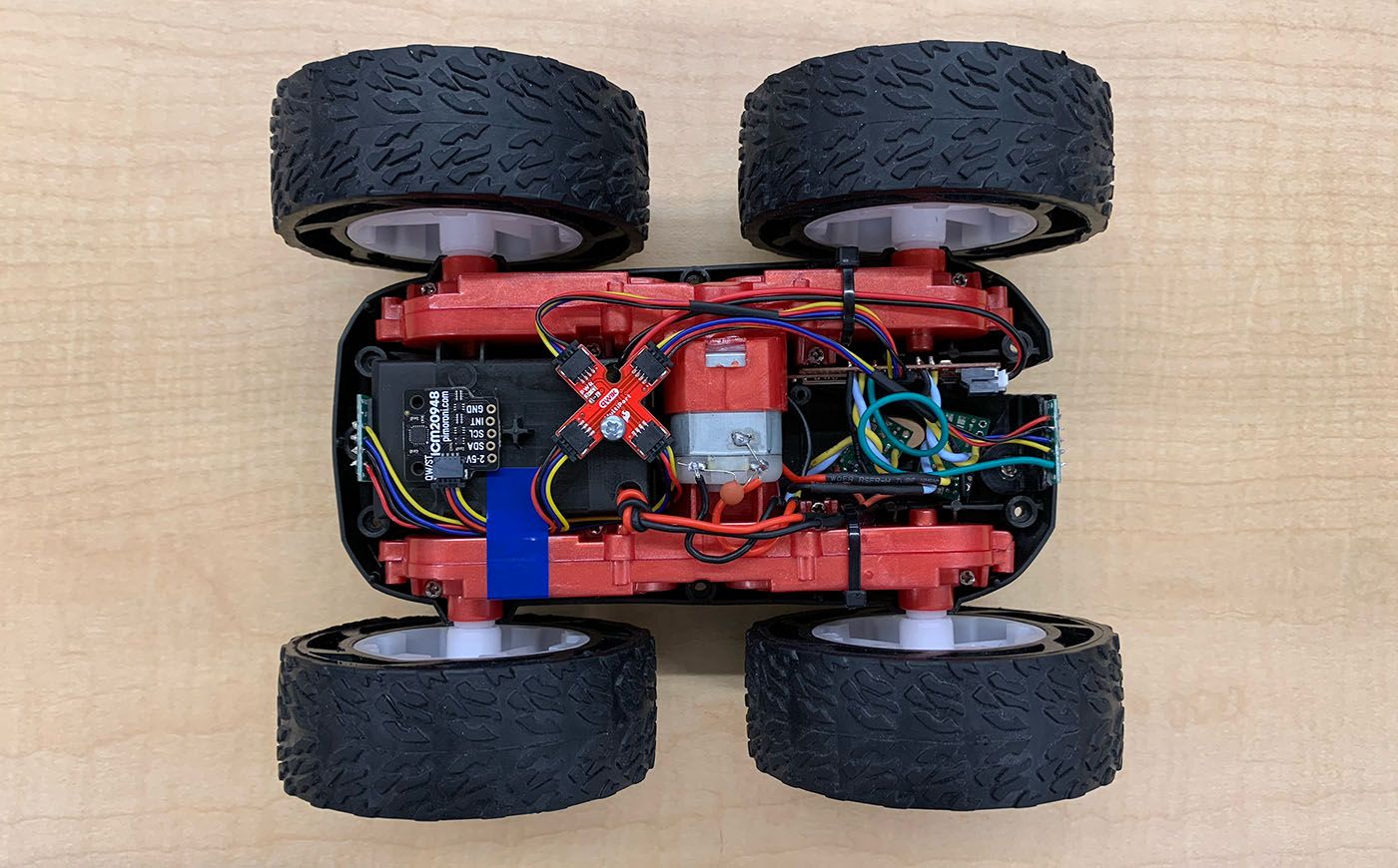
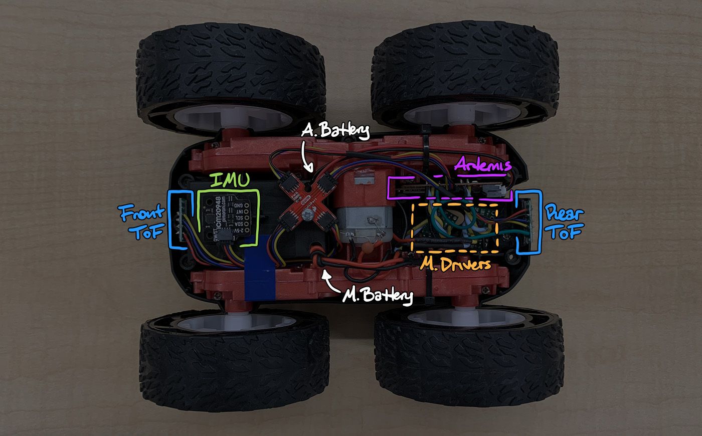
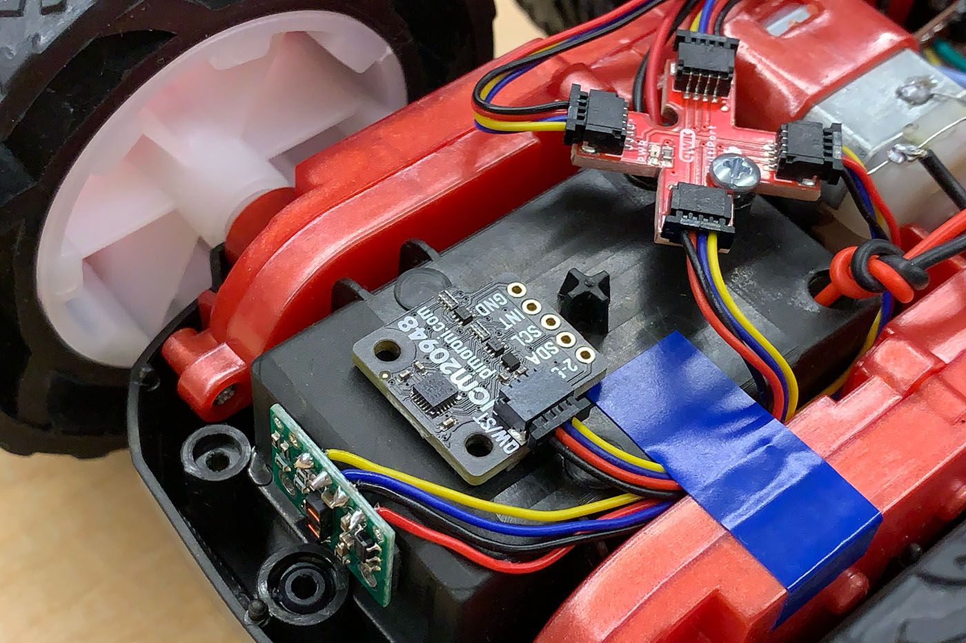
At what I consider the front of the car, I attached one of the ToF sensors, the IMU, and the Qwiic MultiPort. The battery compartment served as a convenient surface to place sensors in relatively orthogonal orientations.
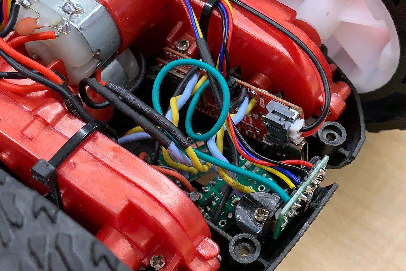
At the rear of the car, I tucked the Artemis and the two motor drivers into the empty space previously occupied by the factory PCB.
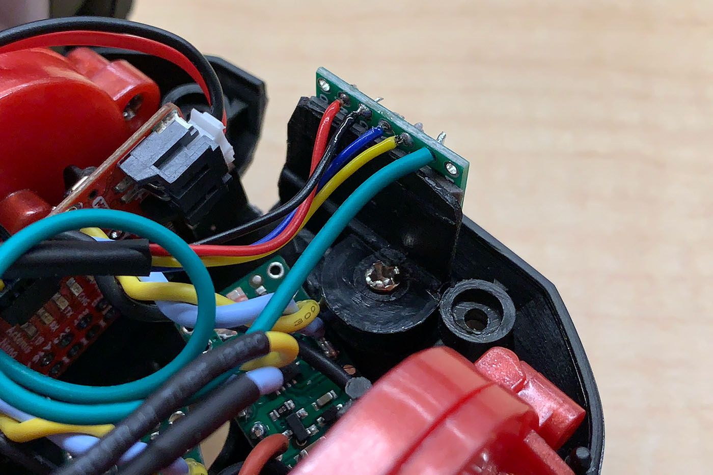
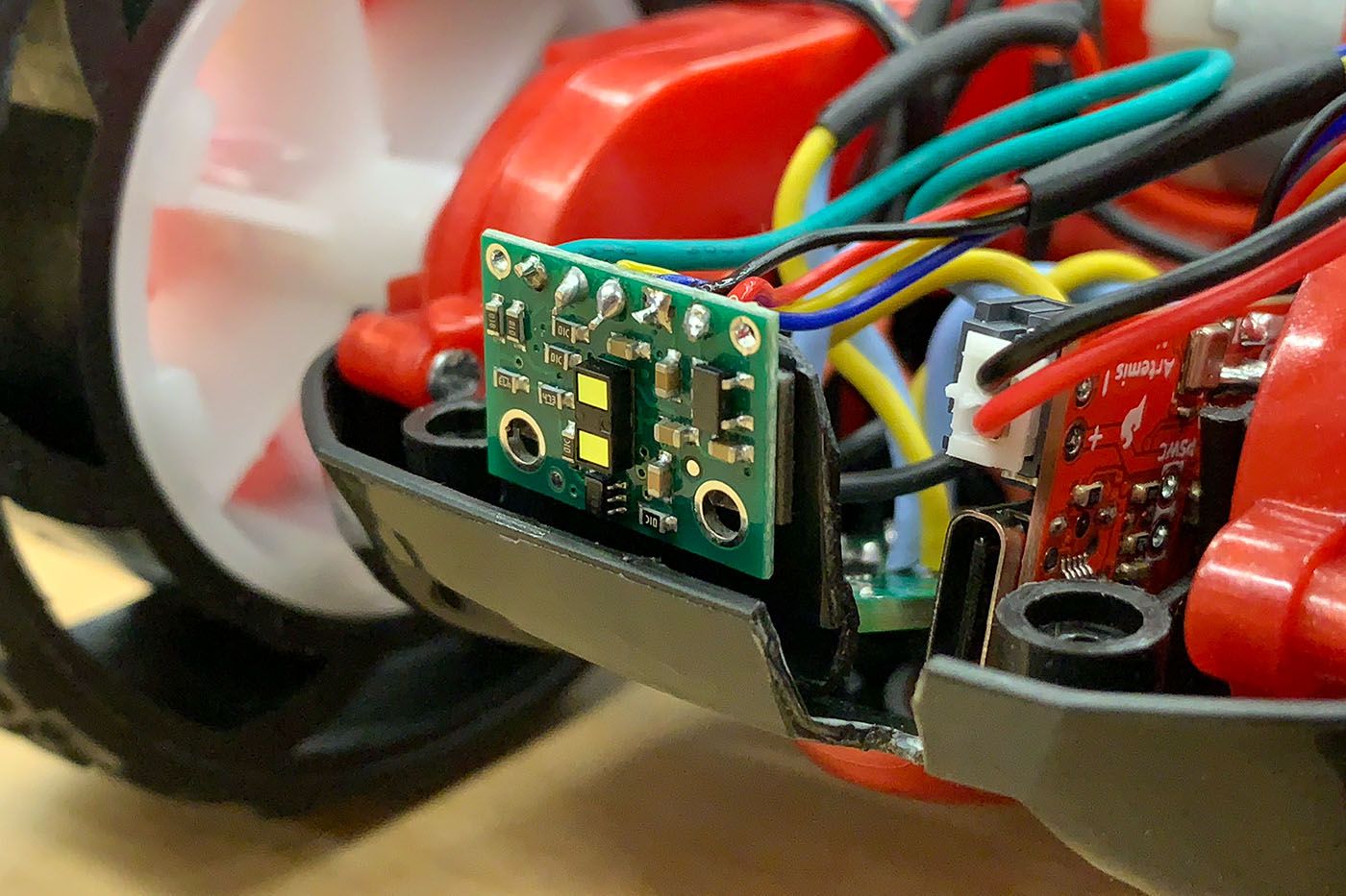
For the rear ToF sensor, I didn't like the idea of attaching the little board to the outside of the chassis, so I cannibalized the car's plastic remote (that was now useless) to make a small angle bracket with a screw hole in it. I screwed this custom part to one of the old PCB's mounting points and attached the second ToF sensor to its rear face.
I then added a DRIVE Bluetooth command to the Artemis to drive the untethered car forward a short distance.
// In handle_command():
case DRIVE:
    analogWrite(MOTOR_LEFT_FWD, 100);
    analogWrite(MOTOR_RIGHT_FWD, 100);

    delay(500);

    analogWrite(MOTOR_LEFT_FWD, 0);
    analogWrite(MOTOR_RIGHT_FWD, 0);

    break;
Calling DRIVE in Python sent the car rolling, albeit veering a little to the left.
Task 8: PWM Limits
With the car resting on the ground, it took PWM values of roughly 35 for the right motor and 50 for the left to overcome static friction and start moving roughly straight. I believe some of this discrepancy comes from differences in friction in the gear boxes; my car's right set of wheels spins much more freely than the left, so the right side needs less power to drive.
Turning is another matter. It seems that because the right and left pairs of wheels are geared together—making the car's steering differential—there is significantly greater amounts of friction to overcome when I attempt to drive the pairs in opposite directions to facilitate a turn. It took PWM values of roughly 115 for the right motor and 130 for the left to turn on-axis from rest. I suspect taping the wheels may help with this by reducing friction and allowing skidding.
Task 9: Straight Ahead
While finding the PWM values to get the car moving in the previous task, it became clear to me that the two motors would need to run at fairly different power levels to be synchronized enough to drive straight. I already had the minimum PWM values, so I continued testing to find that maximum values that kept the car moving in a line were 215 for the right motor and 255 for the left.
With the functional ranges of PWM values found, I wanted a method to translate percentage speeds into PWM equivalents. This way, I could specify, say, 50% speed to each motor without having to remember the conversion to balance the two. It seems better to map the tested minimums and maximums rather than use a single calibration factor because the ratio between the two motors changes throughout their range.
To implement this approach on the Artemis, I wrote a driveMotors() function.
#define SPEED_LEFT_MIN 50
#define SPEED_LEFT_MAX 255
#define SPEED_RIGHT_MIN 35
#define SPEED_RIGHT_MAX 215

void driveMotors(float left_speed, float right_speed) {
    // Clamp speed between -100 and 100 percent
    left_speed = constrain(left_speed, -1, 1);
    right_speed = constrain(right_speed, -1, 1);

    // Drive left motor
    analogWrite(
        // Determine desired direction
        (left_speed < 0) + MOTOR_LEFT_FWD,
        // Set power to output pin
        (left_speed != 0) * (abs(left_speed) * (SPEED_LEFT_MAX - SPEED_LEFT_MIN) + SPEED_LEFT_MIN)
    );
    // Disable opposite direction pin
    analogWrite((left_speed > 0) + MOTOR_LEFT_FWD, 0);

    // Drive right motor
    analogWrite(
        // Determine desired direction
        (right_speed > 0) + MOTOR_RIGHT_BWD,
        // Set power to output pin
        (right_speed != 0) * (abs(right_speed) * (SPEED_RIGHT_MAX - SPEED_RIGHT_MIN) + SPEED_RIGHT_MIN)
    );
    // Disable opposite direction pin
    analogWrite((right_speed < 0) + MOTOR_RIGHT_BWD, 0);
}
Putting the above to the test, I set the right and left motors to 25% speed and drove the car in a straight line down a hallway roughly 14 ft long. The edges of the wooden boards in the floor were my reference here because they are perfectly parallel the entire length of the hallway.
Task 10: Open Loop
What's the fun in all this soldering and calibrating if not to drive the car in a lopsided square to demonstrate open loop control? Well, here we are, and I did just that by adding an OPEN_LOOP command to the Artemis that drives the car forward, turns left, and repeats several times.
// In handle_command():
case OPEN_LOOP:
    for (int i = 0; i < 8; i++) {
        // Move forward
        analogWrite(MOTOR_LEFT_FWD, 100);
        analogWrite(MOTOR_RIGHT_FWD, 65);
        delay(500);
        analogWrite(MOTOR_LEFT_FWD, 0);
        analogWrite(MOTOR_RIGHT_FWD, 0);
        delay(1000);

        // Turn left
        analogWrite(MOTOR_LEFT_BWD, 200);
        analogWrite(MOTOR_RIGHT_FWD, 130);
        delay(500);
        analogWrite(MOTOR_RIGHT_FWD, 0);
        analogWrite(MOTOR_LEFT_BWD, 0);
        delay(1000);
    }

    break;
I then called OPEN_LOOP in Python and watched the magic unfold.
Conclusion
This lab was very hardware-focused, but I'm glad to have had this chance to put together a solid assembly on which I can develop the necessary software in future labs. Being new to soldering, I found several of these tasks to be challenging, time consuming, and even frustrating sometimes, but I learned a lot and I'm quite proud of what I've managed to build.