In Lab 3, I added a battery and two VL53L1X Time-of-Flight (ToF) sensors to the Artemis, then tested the sensors' capabilities, range, and accuracy.
Prelab
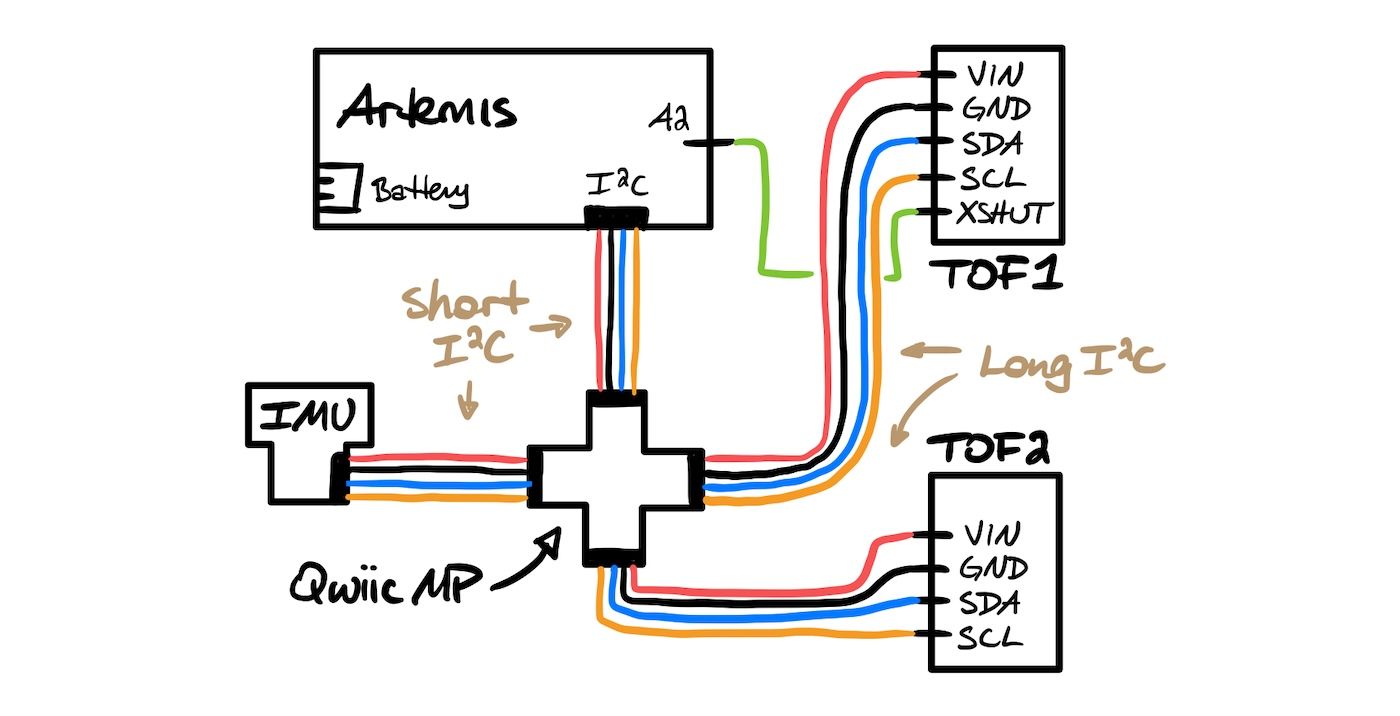
I started by planning out how to use two Pololu VL53L1X ToF sensors with my Artemis through a Qwiic MultiPort connector. Looking over the datasheet, I noticed that the default I2C address of the VL53L1X sensors is 0x52.
Because the ToF sensors have the same default I2C address, communicating with two of them simultaneously will require a change of address routine. My approach for this will be to use the XSHUT pin of one of the two sensors to disable it temporarily, while sending an address change command over I2C to the other. I will need to wire the XSHUT pin to one of the Artemis GPIO pins to control the sensor state programmatically. Alternatively, I could wire the XSHUT pin of both sensors, but I believe this is unnecessary because I can leave the second sensor disabled until I'm sure the first address is changed.
With the provided lengths of I2C cables bridged by the Qwiic MultiPort, I can place the ToF sensors just about anywhere on the 6-inch-long body of the robot. I anticipate that placing the two sensors on opposite ends of the car—one facing forward, one facing backward—will be most useful for future labs. A side-mounted sensor could also be desireable to detect obstacles next to the robot, but this is only true if the obstacle happens to be on the same side as the sensor. In the end, I'll have to stop and spin the car to sense in 360 degrees anyway. So, for now, I stand by my forward- and rear-facing ToF placements.
When wiring the ToF sensors, I will have to make the I2C connections to the sensors permanent because there are no Qwiic connectors on the ToF boards. The XSHUT connection will also need to be permanent because the Artemis GPIO pins are really just soldering pads. The remaining connections—the battery JST and all Qwiic ports—can stay detachable, which may prove useful when finalizing the arrangement of components on the robot. When placing the ToF sensors, the emitter modules will need to face outward, so the soldered wires should protrude from the backs of the boards.
Tasks
Task 1: Battery Power
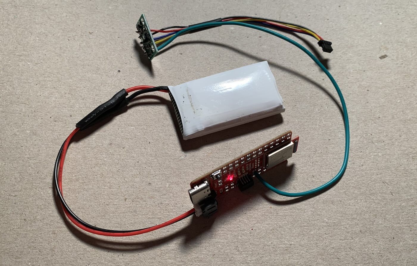
Someday soon, my Artemis and its sensors will be attached to the RC car without a tether to my Mac. To prepare for this, I soldered a JST connector to a 3.7 V battery and used it to power the Artemis sans USB cable. I then used the ECHO command from Lab 1 to check the BLE connection.
Task 2: ToF Connections
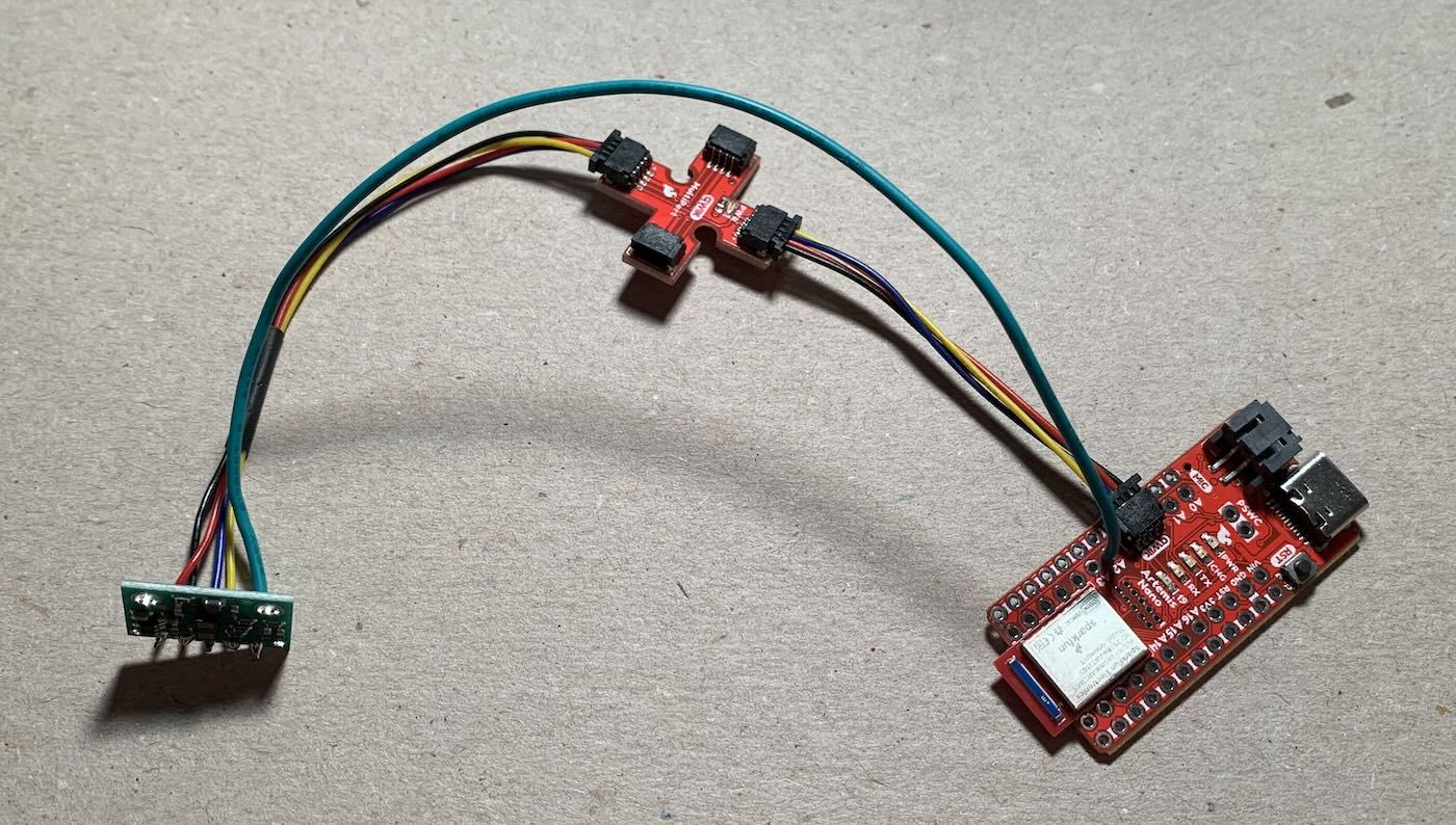
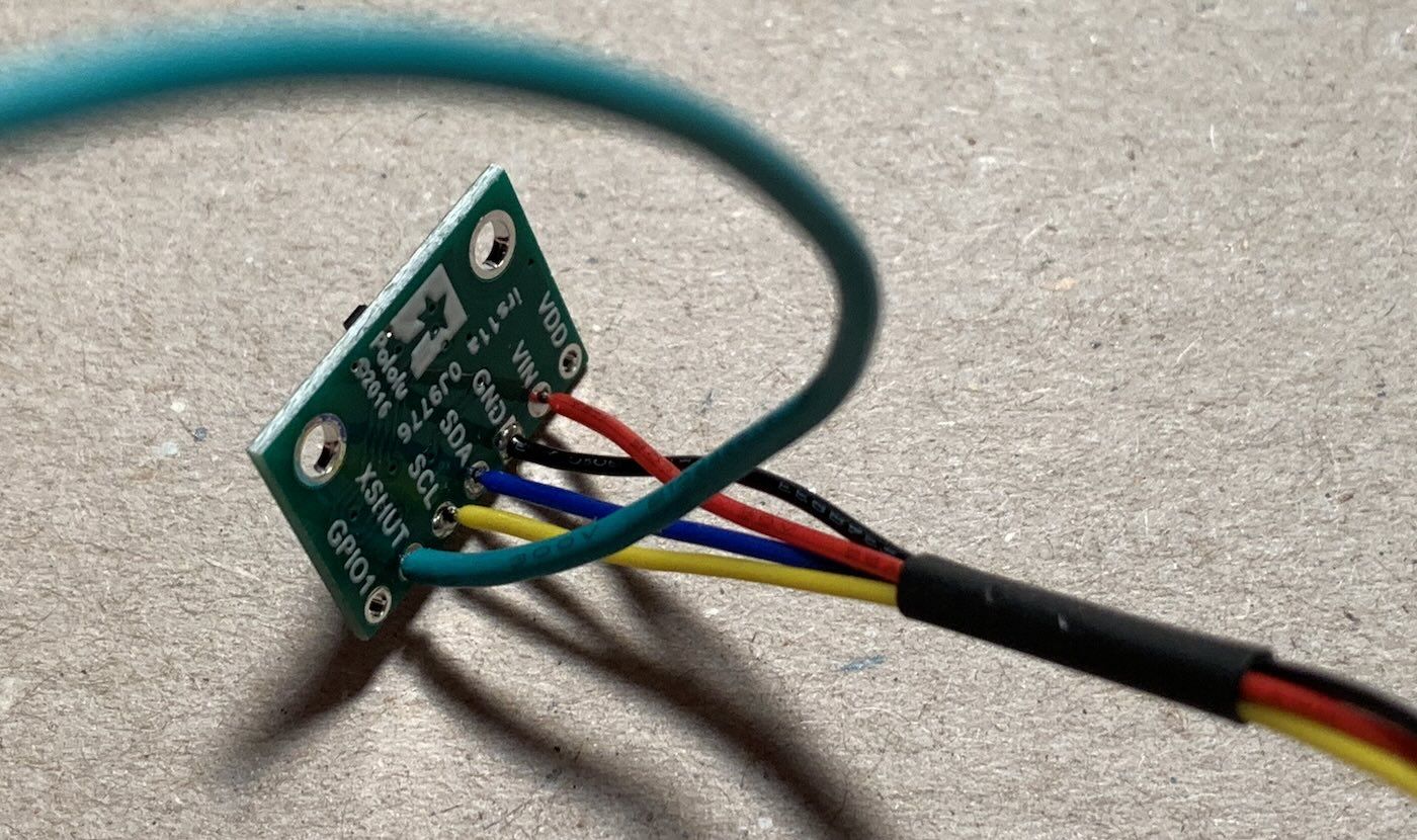
To connect the ToF sensors to the Artemis, I soldered a long Qwiic cable to the contacts on each of the ToF boards, such that:
VIN→ red wireGND→ black wireSDA→ blue wireSCL→ yellow wire
Task 3: I2C Scanning
With the first ToF sensor connected, I scanned for I2C addresses using the example sketch Apollo3 > Example05_Wire_I2C.
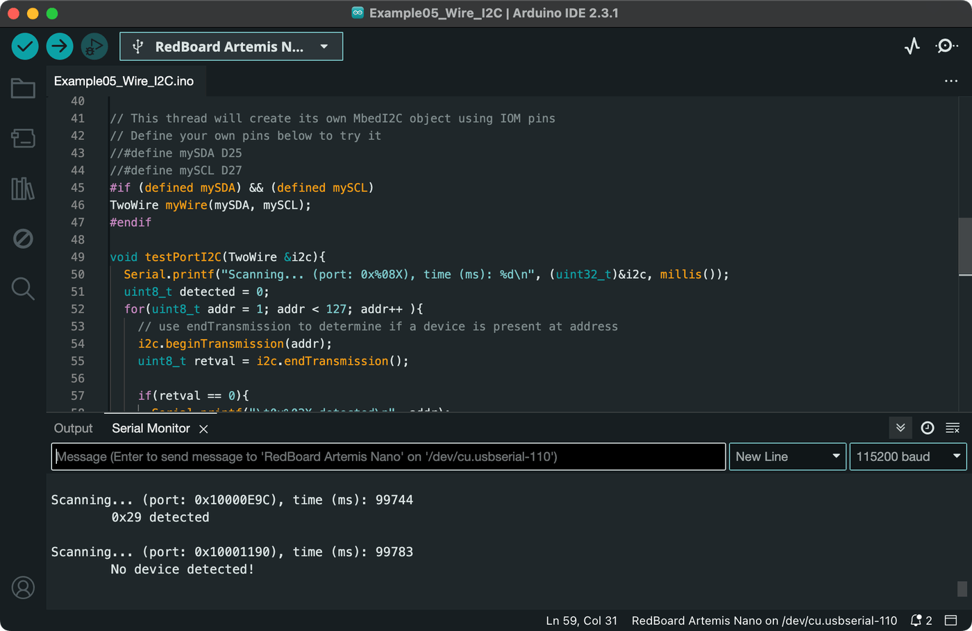
Based on the datasheet, I had expected the ToF sensor to respond to an address of 0x52 (82), but the scan yielded 0x29 (41). This is because the least significant bit of the address packet is used for read/write direction status of the I2C interface. When represented without this last bit, as in the scan above, the remaining address is bit shifted to the right (0b1010010 → 0b0101001), an operation equivalent to halving the decimal value.
Task 4: Sensing Modes
I installed the latest version of the SparkFun VL53L1X Arduino library, which supports two modes for sensing distance: short and long. The long mode can measure up to 4 meters but is disturbed by strong ambient light at large distances, while the short mode is less susceptible to ambient light but can only measure up to roughly 1.3 meters. The tradeoff here is between range and lighting conditions.
Since we will be operating our robot at various times of day and in different types of artificial lighting in the lab or at home, greater sensor reliability in ambient light via the short mode is the better choice. The robot may not be able to see as far, but when trying to avoid obstacles, it's the short distances that will likely matter more.
Using the example sketch SparkFun VL53L1X > Example1_ReadDistance, and setting the sensor mode with setDistanceModeShort(), I collected ToF sensor readings for a variety of distances.
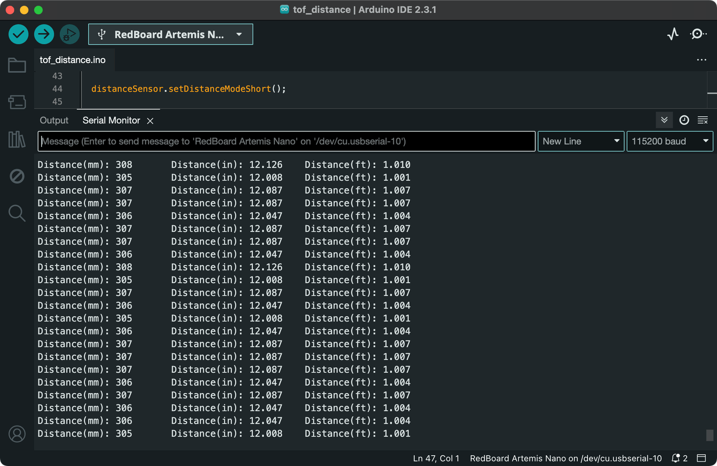
I then calculated the mean, absolute error, and standard deviation for the data taken at each distance. The absolute error—defined as the difference between actual distance and mean reading—yields the accuracy of the sensor, while the standard deviation informs the repeatability of measurements.
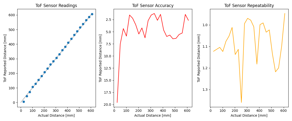
Based on the trends in the plot above, the sensor is not terribly accurate nor reliable at very close distances. This confirms the minimum bound of 4 cm in the datasheet. In fact, a practical lower limit of 10 cm might be advisable. At larger distances well within the short mode range, the sensor has fairly low error at around 4 mm and good repeatability at around 1.1 mm.
Next, I collected readings over a larger range of distances to test the upper limits of the ToF sensor in short mode.
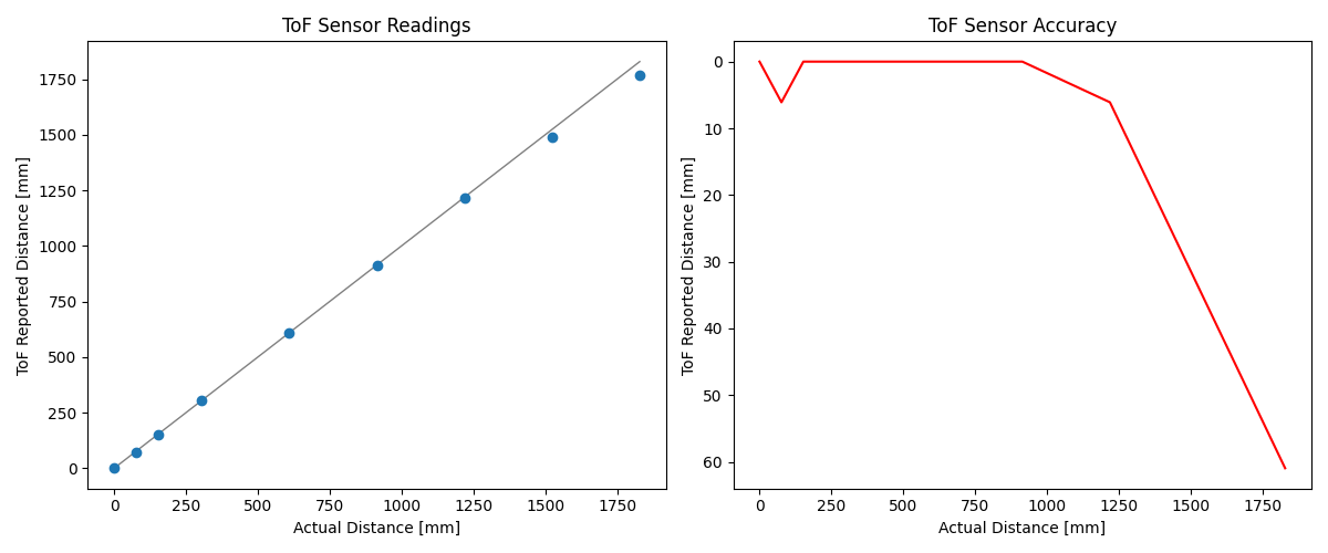
This plot shows that error starts to rise dramatically past about 1.2 meters, which is again consistent with the maximum specification of 1.3 meters for short mode in the datasheet. The sensor will give roughly valid readings beyond that bound, but these should not be trusted as accurate.
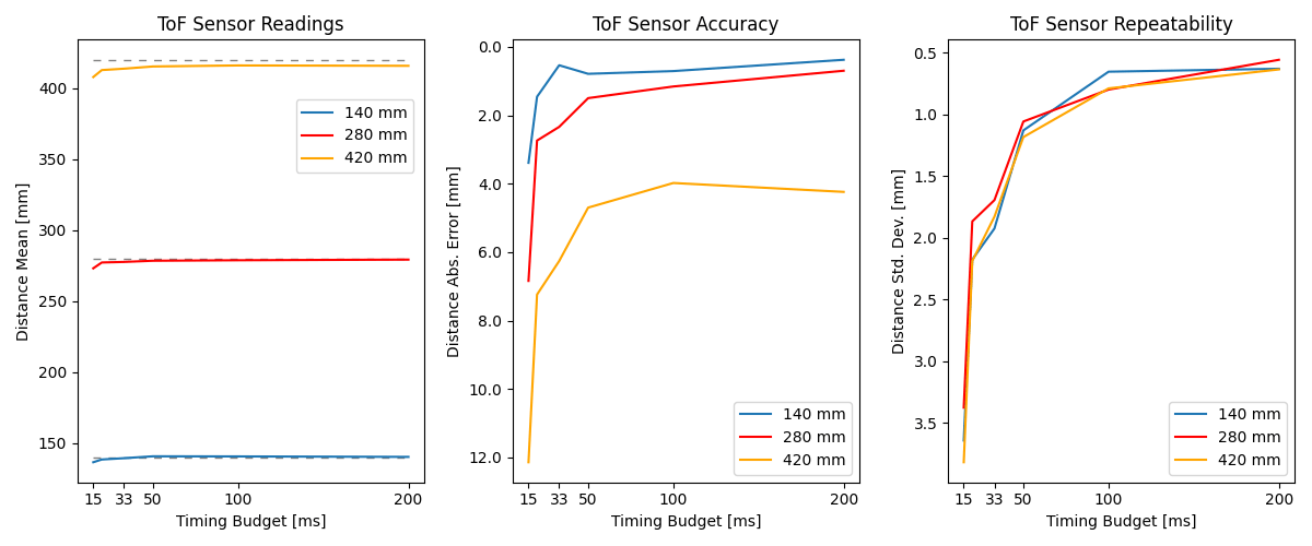
To determine the effects of ranging time, I collected measurements for several timing budgets at each of three distances. Plotting the results, the trends indicate that higher timing budgets are more accurate and repeatable, but this comes at a cost of increased impact on the maximum control loop speed.
Task 5: Parallel Sensors
With one ToF sensor working, I connected the second sensor and additionally soldered a connection between the sensor's XSHUT pin and GPIO pin 2 on my Artemis. I then added logic to my setup() function to initialize the two sensors sequentially while setting a non-default address of 0x48 on the first.
// Shutdown pin and address for ToF1
#define XSHUT_PIN 2
#define TOF1_ADDRESS 0x48

SFEVL53L1X TOF1;
SFEVL53L1X TOF2;

void setup() {
    ...

    // Turn off ToF2
    digitalWrite(XSHUT_PIN, LOW);

    TOF1.init();

    // Try an address change. This either succeeds, or it
    // fails because the sensor remembered its old address.
    // Either way, the address is correct and we can move on.
    TOF1.setI2CAddress(TOF1_ADDRESS);

    if (TOF1.begin() != 0) {
        Serial.println("Sensor 1 failed.");
        return;
    }

    // Turn on ToF2
    digitalWrite(XSHUT_PIN, HIGH);

    if (TOF2.begin() != 0) {
        Serial.println("Sensor 2 failed.");
        return;
    }
}
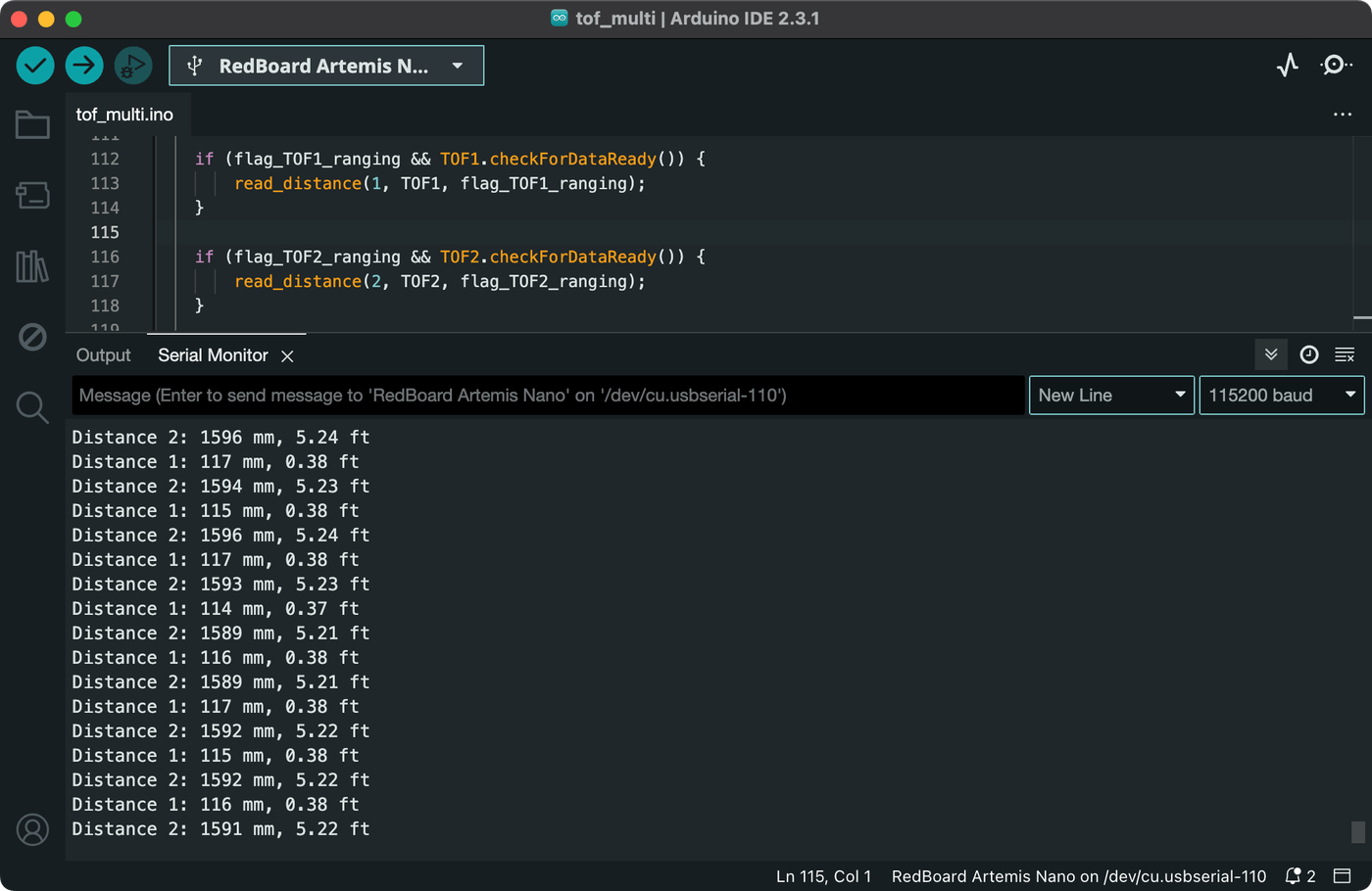
That done, I was able to measure distances from both sensors simultaneously.
Task 6: Sensing Speed
To quantify the speed of the ToF sensors, I changed my loop() function to print the current program time to the serial monitor as quickly as possible and add in the sensor readings whenever they're ready. I also added flags and conditions to enable sensor ranging only when needed.
void loop() {
    Serial.print(micros());
    Serial.print(",");

    // Start ToF1 ranging if not already active
    if (!flag_TOF1_ranging) {
        TOF1.startRanging();
        flag_TOF1_ranging = true;
    }

    // Start ToF2 ranging if not already active
    if (!flag_TOF2_ranging) {
        TOF2.startRanging();
        flag_TOF2_ranging = true;
    }

    // Print ToF1 distance when ready
    if (flag_TOF1_ranging && TOF1.checkForDataReady()) {
        Serial.print(TOF1.getDistance());
        TOF1.clearInterrupt();
        TOF1.stopRanging();
    }

    Serial.print(",");

    // Print ToF2 distance when ready
    if (flag_TOF2_ranging && TOF2.checkForDataReady()) {
        Serial.print(TOF2.getDistance());
        TOF2.clearInterrupt();
        TOF2.stopRanging();
    }

    Serial.println();
}
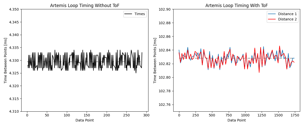
Running the above for a few seconds showed that program times can be printed every 4.3 ms or so, but that the interval between sensor readings is closer to 103 ms. This suggests a printing rate of 233 Hz and a distance sensing rate of only 9.7 Hz. The limiting factor here is clearly the ToF sensors, which can only be read when data is ready. That said, the sensors are advertised for 50 Hz, yet the Artemis is unable to achieve that rate. This may be explained by delays introduced by C++ function calls, or perhaps some implementation factors in the SparkFun VL53L1X library, or even the ToF sensors' ranging times.
Task 7: Bluetooth
The last of my tasks was to incorporate the ToF data into the Bluetooth transfer system I've developed over the last few labs. To do this, I added two more flag-managing commands to the Artemis, START_TOF_DATA and STOP_TOF_DATA.
// In handle_command():
case START_TOF_DATA:
    Serial.println("Recording TOF data...");
    digitalWrite(LED_BUILTIN, HIGH);
    flag_record_tof = true;
    break;

case STOP_TOF_DATA:
    flag_record_tof = false;
    digitalWrite(LED_BUILTIN, LOW);
    Serial.println("Stopped recording TOF data.");
    break;
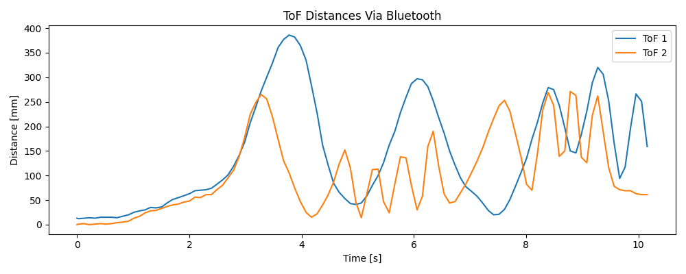
I then called SEND_TOF_DATA in Python and plotted the distances over time.
Optional 5000-Level: Other Sensors
Infrared-based distance sensors generally all operate by emitting infrared waves and detecting the reflections. Whereas ToF sensors use time or phase differences to calculate the distance traveled by a laser pulse, so-called "IR" distance sensors measure the angle of reflection to triangulate distances. Both ToF and IR sensors are very common and low in cost. Another type of distance sensor in the infrared family is LIDAR, which also operates on a laser-pulse timing principle, but is far more precise and therefore much more expensive.
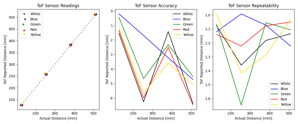
Optional 5000-Level: Color and Texture
The ToF sensors seem to operate fairly consistently when sensing objects of different textures and colors. Color was a straightforward variable to test systematically, so I took various ToF measurements and plotted the results. Both the accuracy and reliability are within the norm found earlier.
Conclusion
This lab has had me thinking about how limited our robots' ability to see their environments will be. Even with two ToF sensors, the cars will need to spend a good deal of time scanning objects in their vicinity by spinning in circles and collecting distance information. By scanning, we could then build a map in the robot's memory with which to, for example, navigate to a target objective.