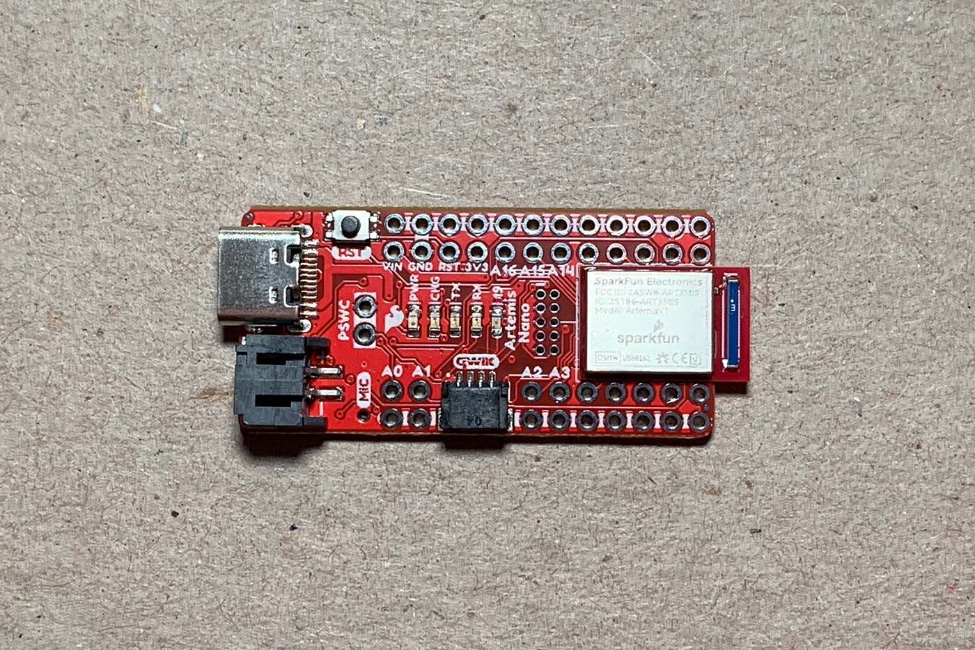
The SparkFun RedBoard Artemis Nano is a compact microcontroller equipped with 17 I/O pins, 8 analog-to-digital conversion channels, 2 asynchronous receiver/transmitters, 4 I2C buses, 2 serial buses, a pulse density microphone, Bluetooth connectivity, and a Qwiic connector.
In Part A of Lab 1, I configured my MacBook for Artemis development and tested some of the board's features.
Prelab
To prepare for Part A of the lab, I installed the latest Arduino IDE (v2.2.1) on my Mac running macOS 12 Monterey.
Tasks
Task 1: Installation
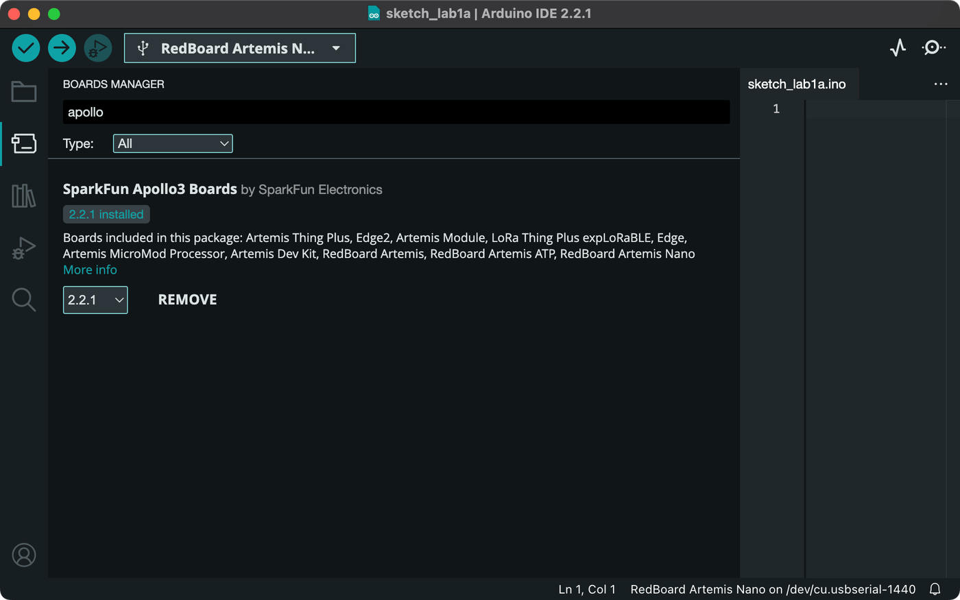
I started the lab by connecting the Artemis Nano to my Mac via USB C. I then followed the Artemis setup instructions provided by SparkFun. Based on those instructions, I added SparkFun's Apollo3 Arduino Core to the Board Manager in Arduino IDE and then installed the "SparkFun Apollo3" board package.
Task 2: Blink
To confirm the Artemis board installation, I ran the Arduino IDE "Blink" example sketch, Examples > 01.Basics > Blink, which switches the board's built-in LED on and off on a one-second cycle.
Task 3: Serial
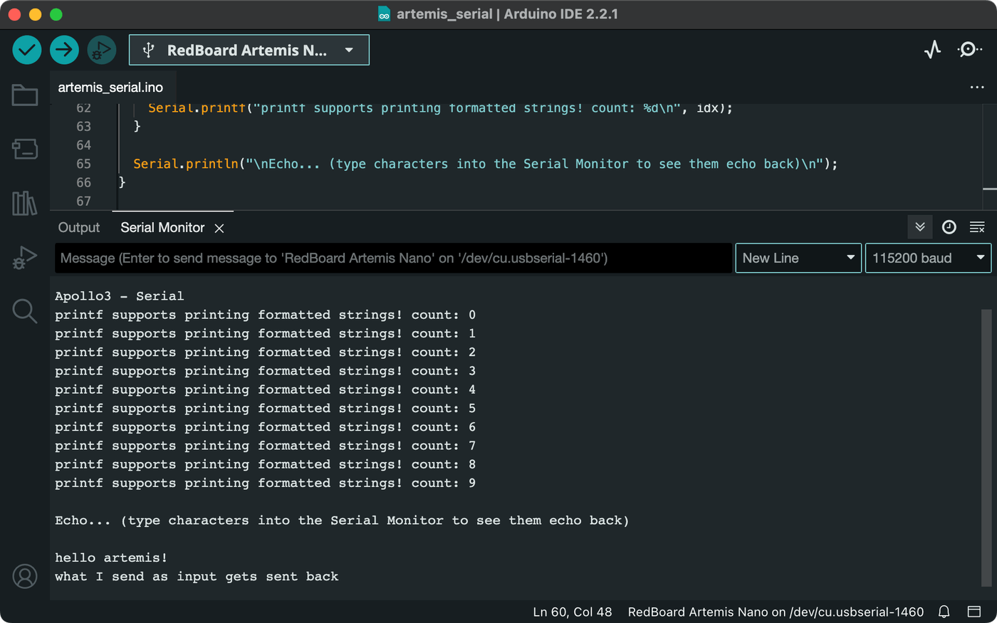
To test serial communication, I uploaded the Artemis "Serial" example sketch, Examples > Apollo3 > Example04_Serial, which prints a few messages and then listens for inputs to echo back. To match the sketch, I set the serial monitor baud rate to 115200.
Task 4: Temperature
The Artemis board has an integrated temperature sensor. To test it, I ran the Artemis "AnalogRead" example sketch, Examples > Apollo3 > Example02_AnalogRead, which continuously prints a raw temperature sensor reading to the serial monitor.
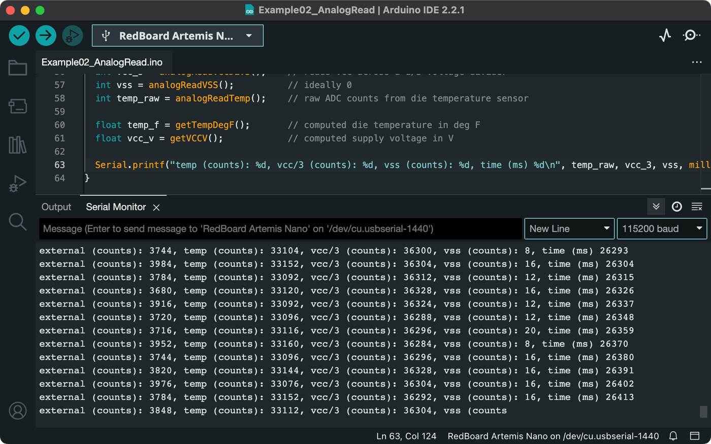
The raw temperature data isn't particularly human-friendly, so I modified the example sketch to instead print readings in Celsius and Fahrenheit.
// Serial.printf("temp (counts): %d, ...\n", temp_raw, ...);
Serial.print("deg_C:");
Serial.print(getTempDegC(), 2);
Serial.print(",deg_F:");
Serial.println(getTempDegF(), 2);
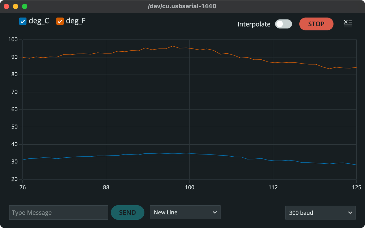
I then used the Arduino IDE serial plotter feature to visualize the temperature data in real time while warming the Artemis with my hand.
Holding the Artemis only had a modest effect on the temperature reading, so I tried placing the board near a light bulb and then taking it away again while plotting at a very slow baud rate of 300. This approach induced a more dramatic trend in the data over time.
Task 5: Microphone
For the last example, I uploaded the Artemis "MicrophoneOutput" sketch, Examples > PDM > Example1_MicrophoneOutput, which continuously reports the loudest frequency the microphone detects at any given moment.
To test the microphone against a source of known frequencies, I used a piano simulator on my Mac to play three notes: F4 (349 Hz), A4 (440 Hz), and C5 (523 Hz). I played a somewhat random sequence, repeating each note twice overall. The microphone measured the frequencies fairly accurately, reporting 354 Hz, 446 Hz, and 526 Hz for the notes, respectively.
Optional 5000-Level: Musical Tuning
I'm enrolled in the 4000-level course, but I wanted to try out the extra material. To have the onboard LED illuminate when playing a musical note "A", I modified the "MicrophoneOutput" example sketch from Task 5. I first set the LED I/O pin to output mode.
// In setup():
pinMode(LED_BUILTIN, OUTPUT);
I then defined a few variables: the target frequency of 440 Hz for an A4 note, a high-pass cutoff to avoid low frequency noise, and an approximation factor to account for slight variance in the microphone readings. I used these values to test for an A4 and set the voltage on the LED accordingly.
// In printLoudest():
uint32_t ui32Note = ui32LoudestFrequency;
uint16_t freqA4 = 440; // LED frequency
uint8_t cutoff = 20;
uint8_t blur = 7;

bool isA4 = ui32Note > freqA4 - blur && ui32Note < freqA4 + blur;
digitalWrite(LED_BUILTIN, isA4 ? HIGH : LOW);
With detection of one note complete, I further modified the sketch to define frequencies for the remaining notes in the fourth standard octave (C4 - B4).
uint16_t freqC4 = 262;
uint16_t freqCs4 = 277;
uint16_t freqD4 = 294;
uint16_t freqEb4 = 311;
uint16_t freqE4 = 330;
uint16_t freqF4 = 349;
uint16_t freqFs4 = 370;
uint16_t freqG4 = 392;
uint16_t freqAb4 = 415;
uint16_t freqA4 = 440; // LED frequency
uint16_t freqBb4 = 466;
uint16_t freqB4 = 494;
I wanted to make the tuner effective for more than just this specific set of pitches. Because the frequency of any given note doubles or halves when ascending or descending octaves, respectively, I could detect a wide range of notes with two loops to modulate the loudest frequency measured by the microphone to an equivalent pitch in the fourth octave.
// Repeatedly double the frequency up until the fourth octave
while (ui32Note > cutoff && ui32Note < freqC4 - blur) {
    ui32Note *= 2;
}

// Repeatedly halve the frequency down until the fourth octave
while (ui32Note > cutoff && ui32Note > freqB4 + blur) {
    ui32Note /= 2;
}
I then used the modulated frequency and the defined set of pitches to conditionally print the corresponding note to the serial monitor.
if (ui32Note < freqC4 + blur) {
    Serial.print("C");
}

if (ui32Note > freqCs4 - blur && ui32Note < freqCs4 + blur) {
    Serial.print("C#");
}

if (ui32Note > freqD4 - blur && ui32Note < freqD4 + blur) {
    Serial.print("D");
}

// and so on...
Running this on the Artemis created a pretty decent musical tuner that lights up for the note "A".
Conclusion
This lab has shown me that the Artemis Nano is a nifty little board, somewhat similar to the Arduinos I've worked with in the past. New to me were the integrated temperature sensor and microphone, and I enjoyed the added exercise of making a musical tuner.